


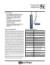
Frequency Response:
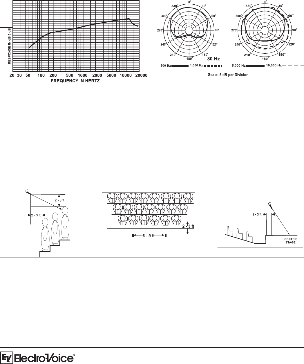
Figure 1: Hanging Mic
Placement
12000 Portland Avenue South, Burnsville, MN 55337
Phone:952/884-4051, Fax:952/884-0043
www.electrovoice.com
© Telex Communications, Inc. 6/2006
Part Number 534912 Rev D
U.S.A. and Canada only. For customer orders, contact Customer Service at:
800/392-3497 Fax: 800/955-6831
Europe, Africa, and Middle East only. For customer orders, contact Customer Service at:
+ 49 9421-706 0 Fax: + 49 9421-706 265
Other International locations. For customer orders, contact Customer Service at:
+ 1 952 884-4051 Fax: + 1 952 736-4212
For warranty repair or service information, contact the Service Repair department at:
800/553-5992 or 402/467-5321
For technical assistance, contact Technical Support at: 800/392-3497 or 952/736-4656
Specifications subject to change without notice.
Figure 2: 3-to-1 Rule
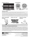
Polar Response:
When hanging one or more microphones to provide coverage for a choir, instrumental or theater group, the best microphone position for optimum sound
quality and feedback control depends on many factors–sound system characteristics, construction of the auditorium or theater, and the size and nature of
the performing group. Two general rules to observe for the best sound coverage are (1) microphone position and (2) the “3-to-1 rule.”
The first rule is to suspend the microphone approximately two to three feet in front of the first row of performers and two to three feet higher than the
heads of the last row of performers. The microphones are usually aimed to point at the last row of performers (see Figure 1). The second rule, the “3-
to-1 rule,” should be applied when more than one microphone is required, and their outputs are combined (as with a mixer). Following the 3-to-1 rule
avoids the deep voids and dips in frequency response that occur when two or more microphones “see” the same signal from slightly different
distances. The 3-to-1 rule is as follows: when multiple microphones are used, place them at least three times as far apart as any one of them is from
the nearest sound source. Figure 2 shows a proper application of the 3-to-1 rule. The RE90H/HW may also be used to provide coverage for live theater
applications (Figure 3). Most of the action occurs at center stage, so the microphone should be positioned above and pointed to the center of the stage.
Application Notes:
Figure 3: Live Theater
Placement
Architectural and Engineering Specifications
The microphone shall be a back-electret condenser type with a frequency response of 75 Hz to 15 kHz. The microphone shall have a
cardioid polar pattern with a rear response which is typically 15 dB below the front response at 1.0 kHz. The microphone shall have an
output level of 20mV/pascal, and output shall not be appreciably affected by the following temperature and humidity extremes: -29° to
74° C (-20° to 165°F) when the relative humidity is 0-50%; -29° to 57° C (-20° to 135° F) when relative humidity is 0-95%. The microphone
shall have a nominal, balanced output impedance of 200 ohms when connected to its electronics module. The microphone shall have
a low-gloss black finish (RE90H) or a low-gloss white finish (RE90HW). The cable color shall match the transducer. The transducer
shall have a wire hanger for directing the microphone. Dimensions: the transducer shall be 12.7 mm (0.4 in.) wide and 36.8 mm (1.4
in.) long; the cable shall be 7.6 m (25 ft) long and 2.6 mm (0.1 in.) in diameter. The electronics module shall be a metal cylinder 94 mm
(3.7 in.) long and 19 mm (0.75 in.) in diameter. Termination to the electronics module shall be a 3-pin male XLR type connector. The
Electro-Voice RE90H and RE90HW are specified.