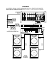
allows the power amplifier to be used independently
from the rest of the SR powered mixer. Possible uses
of this feature include dedicating the power amp to
the monitor system while employing an auxiliary
power amplifier for the mains, or using the SR power
amp as one of the two power amplifiers in a biamped
system (this would require the addition of an external
crossover). See Section 4-5.
3. REAR PANEL
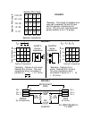
3-1. SPEAKER OUTPUT JACKS(In Parallel). These are
the speaker outputs for the built-in power amplifier.
Do not connect loads with impedances lower than 2
ohms to the SPEAKER OUTPUT, as this may result in
amplifier overheating which will cause the SR mixer to
eventually self protect, “turning off” for a period of
time. (To calculate the speaker impedance, see Section
4-3-2.) In addition, be sure that the speaker cable
you use is of adequate gauge; otherwise, power will
be lost in the wire instead of being delivered to the
speaker.
3-2. POWER SWITCH. AC Power to the SR powered
mixer is turned on and off by a rocker switch located
on the back panel. If you have any external signal
processing devices patched to the system, turn them
on first to avoid pops in the loudspeakers. Also, when
you turn on the mixer, make sure that the main fader
is down - this eliminates the risk of the system imme-
diately feeding back when it is turned on, and also
minimizes turn-on-pops.
3-3. POWER CORD. WARNING! Do not remove the
grounding prong of the AC plug. To do so risks expo-
sure to potentially lethal voltages and voids the war-
ranty. DO NOT ALTER THE AC (MAINS) PLUG.
4. SETUP AND OPERATION.
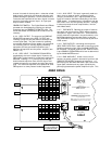
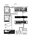
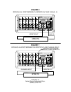
FIGURE 1 illustrates the simplest way to set up your PA
system.
4-1. INITIAL CONTROL SETTINGS. When you first set
up the sound system, initial settings are critical for
arriving at a satisfactory mix quickly. Often, to the
distress of many sound engineers, the show must
begin without a preliminary sound check. The follow-
ing recommendations should help to alleviate some of
the engineer’s headaches.
4-1-1 TYPICAL PRESETS. Set the channel HIGH, MID,
and LOW frequency controls to their mid positions,
and also set the GRAPHIC EQUALIZER to its mid or flat
position. Set the MAIN MASTER and MONITOR MAS-
TER controls to around the 1o'clock position. Set all
other controls to zero.
4-1-2 MAIN CONTROL. Adjust the MAIN controls to
the approximate level you desire, with a mix that you
feel will be acceptable.
4-1-3. MON. CONTROLS. Most groups like to hear
their voices in the monitors; some also like to hear
certain instruments as well (keyboard, acoustic guitar,
and so forth). A good initial MON. control setting is 5
(straight up). Assuming that the various vocalists use
similar miking techniques and sing at similar volumes,
the levels appearing in the monitor mix should be fair-
ly matched. Further adjustments can be made as
needed.
4-1-4. CHANNEL TONE CONTROLS. Most vocal,
keyboard, and other full range signals are best left flat
(controls at 0, or straight up). For signals having a
great deal of low frequency content, such as drums
and bass guitars, the LOW control should
initially be backed off slightly (rotated to the left) from
the 0 position to reduce boominess. Naturally, all
controls should be set to achieve the most pleasing
sounds, but the settings listed above should help in
achieving good results quickly. In general, extreme
settings cause the sound to be unnatural and should
be avoided.
4-1-5. GRAPHIC EQUALIZER. Start out with equalizer
set “flat” (O dB). On the SR mixers, the 63 Hz control
may be set initially 3 to 6 dB below the center position,
since excessive low frequencies rob power from the
rest of the system and low-end feedback can damage
loudspeakers.
4-2. USING THE GRAPHIC EQUALIZER TO ELIMI-
NATE ACOUSTIC FEEDBACK.
4-2-1. THE CAUSE OF ACOUSTIC FEEDBACK.
Acoustic feedback in a sound system is the result of
coupling between the speakers and microphones. The
microphones will always pick up a certain amount of
signal from the speakers; how much they pick up
depends on the room acoustics, the frequency
response of the microphones and speakers, and the
mic and speaker placement. If the received signal is
amplified enough (in the mixer and power amplifier),
the speakers will continue to produce the signal, and
the characteristic howl of acoustic feedback will begin.
This feedback will occur at the frequency which
receives the largest amount of gain from the sound
system (including the room). If the signal can be
attenuated at that frequency, more gain can be added
to the rest of the signal frequencies before feedback
occurs. This is the primary role of an equalizer in a
sound system.
4-2-2. TYPICAL PROCEDURE FOR ROOM EQUALIZA-
TION.
1. Set up your entire sound system the way it will be
used, including all auxiliary equipment, and adjust it
the way you would normally use it. If feedback occurs
during setup, reduce the gain of the mixer with the
MAIN and MONITOR level controls. Follow the proce-
dure outlined in the paragraphs below, first for the
main system and then for the monitors (assuming you
are using an equalizer in your monitor system, which
is highly recommended).
2. Set the controls on the GRAPHIC EQUALIZER to the
“flat” position, indicated as “0 dB” on the panel.
3. Slowly increase the output level (using the appro-
priate level control) until the sound system is on the
threshold of feedback - a ringing sound will occur
when you tap on the microphones.


