


7
◊
◊
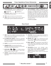
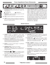
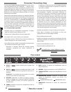
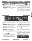
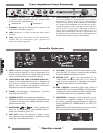
Rear Panel
Trans-Impedance Power Attenuator
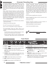
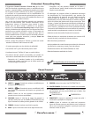
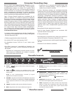
K. OVERDRIVE ONOFFPress IN to engage the Overdrive
circuit as indicated by the LED. See FOOTSWITCH {Z}.
OVERDRIVE Off OVERDRIVE On
L. OVERDRIVEAdjusts the amount of signal distortion
provided by the Overdrive effect.
M. TONEAdjusts the Overdrive tone characteristics.
N. LEVELAdjusts the Overdrive volume output, useful for
boosting gain to generate additional tube distortion.
O. TRANSIMPEDANCE POWER ATTENUATORWhen
set to FULL VOLUME, the attenuator circuit is bypassed
allowing the maximum output from the tube ampli-
fier. When set to SILENT, the speaker is disabled, but
HEADPHONE and LINE OUT outputs may be used. At
any setting beside FULL VOLUME (including SILENT) the
power attenuation circuit controls the output loudness
of the speaker, while preserving the tube amp + speaker
“feel” and dynamics achieved through amplifier volume
and playing intensity.
(US PATENT # 6,816,009)
P. FUSE
Protects the amplifier from electrical faults. Only
replace a blown fuse with the type and rating specified
on the rear panel of your amplifier.
Q. IEC POWER INPUT SOCKETConnect to a grounded
outlet using the supplied power cord in accordance with
the voltage and frequency ratings specified on the rear
panel of your amplifier.
R. POWERTurns the Princeton Recording-Amp ON-OFF.
S. SPEAKER OUTPUTConnection for the speaker.
CAUTION: An Ω speaker must ALWAYS be connected when
the amplifier is ON or damage may occur.
T. HEADPHONE / A speaker-emulated
output for use with standard Stereo or Mono head-
phones. Accepts a standard /" plug.
U. LINE OUTA studio-quality, speaker emulated, balanced
XLR output suitable for recording or sound reinforcement
applications.
V. LINE LEVEL
Adjusts the output level of the LINE OUT
{U} jack. Use to accommodate the input sensitivity of
your connected equipment.
W. GROUND LIFT Press IN to disconnect the LINE
OUT {U} ground pin () to reduce noise caused by non-
standard wiring. Leave OUT for normal operation.
X/Y
. SEND / RECEIVEEffects loop jacks. Connect SEND {X}
to your effects input and RETURN {Y} to effects output.
Set your effects device level control (if any) as close to
–dBu as possible.
Z. FOOTSWITCHConnect the included -but-
ton footswitch using the supplied -pin DIN cable to
enable remote on-off switching of: OVERDRIVE {K},
COMPRESSOR {H}, FX LOOP {X,Y} and REVERB {F}.
NOTE: The footswitch buttons override the corresponding
panel controls.