


channel is turned all the way down - otherwise a feed-
back loop will exist which could cause oscillation and
possible damage to speakers. Care must be taken to
insure that the amplitude of the return signal is not too
great for the preamp channel input. An input pad
may be used if needed.
REVERB FOOTSWITCH. The Digital Reverb and Effects
processer can be defeated by inserting an optional
footswitch into the REVERB FOOTSWITCH jack. This
allows the Reverb and Effects to be turned off and on
remotely.
2-4-4. GEQ. OUTPUT. The output of the GRAPHIC
EQUALIZER is present at the GEQ. OUTPUT jack;
inserting a plug into this jack does not interrupt the
normal signal path. The jack is useful for patching
more power amplifiers into the system, for post-equal-
izer recording and for inserting signal processing
equipment (limiters, parametric equalizers, etc.)
between the equalizer and the power amplifier (see
Section 4-5).
2-4-5. GEQ. INPUT. The GRAPHIC EQUALIZER is
prepatched to the main output signal. However, the
GEQ. INPUT jack allows this “normalized” patch to be
defeated; inserting a 1/4” phone plug into the jack
disconnects the equalizer from the main signal and
instead connects it to any signal carried by the phone
plug. This allows the equalizer to be patched to other
SR outputs or to other pieces of audio equipment.
2-4-6. AUX. INPUT. This input is generally used as a
return from an external signal processing device
(flanger, phase shifter, etc.). Signals present at this
input are routed to the Main buss by way of the AUX.
LEVEL control. In emergencies, it is possible to use the
AUX. INPUT as a line level preamp channel, although
it lacks the preamp channel’s equalization, monitor,
and effects sends.
2-4-7. TAPE INPUTS. Patching the output of a stereo
tape deck into the two phono (RCA) jacks produces a
monophonic signal in the main mix. This is useful for
playing music during breaks in the performance, or for
performances where prerecorded music is required.
The TAPE INPUTS signal level is controlled by the AUX.
LEVEL control.
2-4-8. TAPE OUTPUTS. connecting the two phono
(RCA) TAPE OUTPUTS to a tape deck’s recording inputs
allows monophonic signal from the MAIN OUTPUT to
be recorded. The signal present at the TAPE OUTPUTS
is pre-GRAPHIC EQUALIZER and its level is determined
by the MAIN MASTER control.
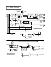
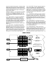
2-4-9. PWR. AMP INPUT. Under normal circum-
stances, the power amplifier receives its input from the
GRAPHIC EQUALIZER. However, by inserting a 1/4”
phone plug into the PWR. AMP INPUT jack, the normal
signal path is broken and any signal carried by the
phone plug becomes the power amplifier’s input. This
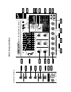
b
b
c
c
d
OFF
CAUTION:
RISK OF ELECTRIC SHOCK
DO NOT OPEN
A PRODUCT OF:
FENDER MUSICAL INSTRUMENTS CORP.,
CORONA, CA 91720
MADE IN U.S.A.
MODEL
TYPE: PR 179
POWER
ON
SPEAKER
OUTPUTS
520 WATTS
2 OHM
MINIMUM
TOTAL
SR6520PD
DSP POWERED MIXER
SERIAL NUMBER
INPUT POWER
INFO
1200W
e
CAUTION: CHASSIS SURFACE HOT
WARNING: TO REDUCE THE RISK OF FIRE OR
ELECTRIC SHOCK, DO NOT EXPOSE THIS EQUIPMENT
TO RAIN OR MOISTURE
AVIS: RISQUE DE CHOC ELECTRIQUE NE PAS OUVRIR
ATTENTION: SUPERFICIE DE CHASSIS CHAUDE
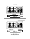
REAR PANEL
3-1
3-1
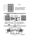
WARNING:
DO NOT ALTER THE
AC (MAINS) PLUG.
3-2
3-3