


a complete stop before removing it from the hole.
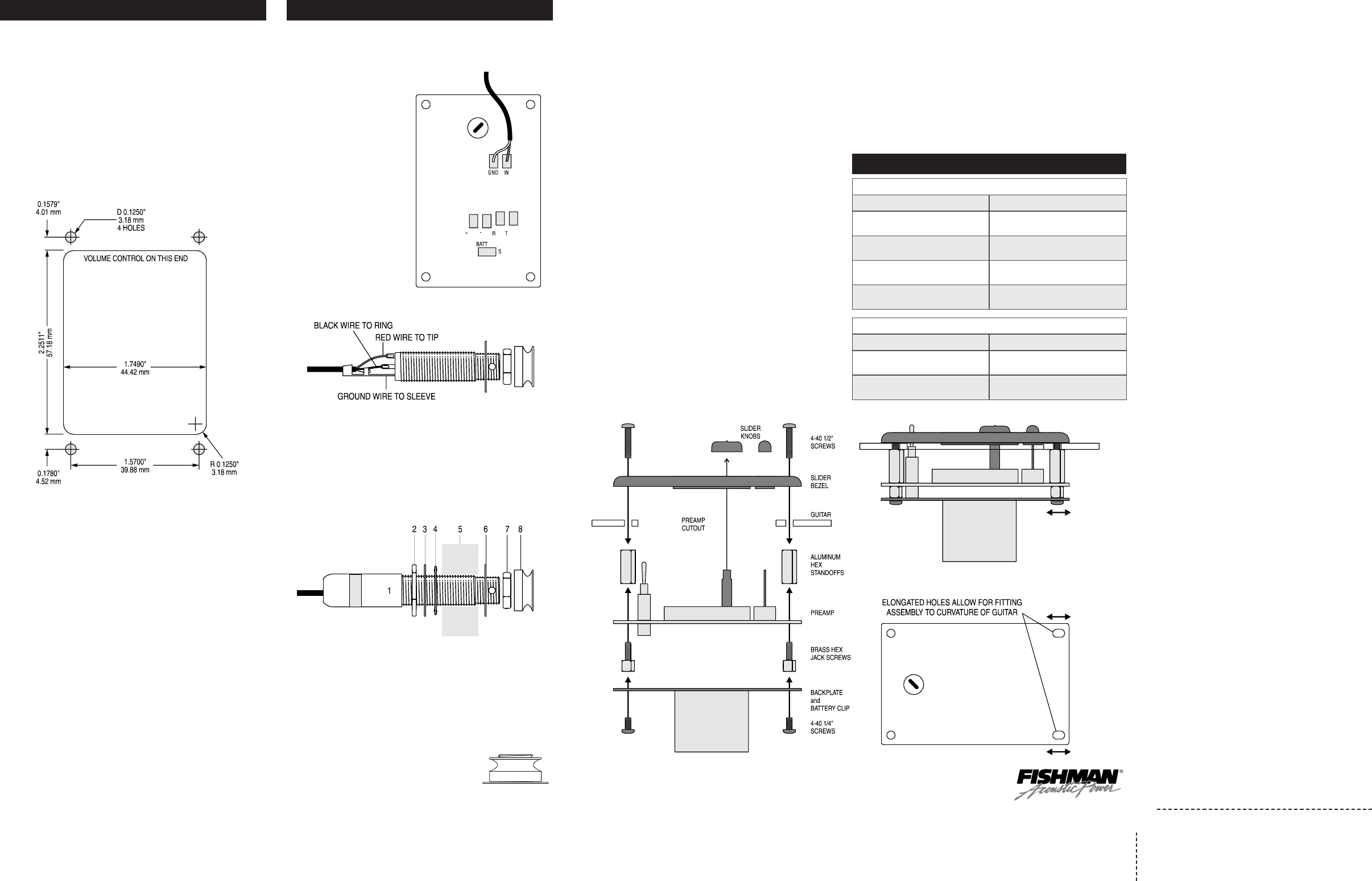
SOLDER THE WIRE CONNECTIONS
1. Insert the pickup in the sad-
dle slot then strip and tin
the wire ends.
2. Solder the "hot" wire from
the pickup (inner conductor)
to the pad marked "IN" on
the preamp circuit board.
Solder the "ground" wire
from the pickup (shield) to
the pad marked "GND" on
the preamp circuit board.
3. Strip and tin the wire ends
of the preamp output cable.
Solder the RED wire to TIP,
the BLACK wire to RING
and the ground wire to the
SLEEVE of the 1/4" jack.
FASTEN THE JACK IN THE ENDPIN HOLE
Follow this sequence when installing the endpin jack:
1 - Shielding Cap
(optional)
2 - First Large Hex Nut
3 - Large Dress Washer
4 - Star Washer
5 - Guitar Endblock
6 - Small Dress Washer
7 - Small Dress Nut
8 -
Strap Button
The jack should protrude at least 5/16" and no more than 11/32" out-
side of the body for proper fit. After fitting the small dress washer and
nut over the end of the jack, insert the 3/32" allen wrench through the
cross drilled hole on the end of the jack. Tighten the nut with the 1/2"
open end wrench while holding the jack in place with the allen wrench.
Thread and hand tighten the the strap button.
NOTE: With the strap button in place, the end of
the jack should protrude slightly to allow proper
plug fit.
MOUNT THE PREAMP
The hardware supplied will accommodate guitars with laminated sides
that are between .100" and .175" thick. If your guitar has sides less
than .100" thick, the slider knobs will not fit in the bezel properly.
To make up the difference, use #4-40 washers to shim the preamp
inside the instrument or contact Fishman for longer standoffs.
1. Fasten the 3/16" brass hex screws and the 1/4" hex standoffs to
the preamp as shown. Note that the mounting holes on the volume
control side of the circuit board are slotted to allow for fitting the
preamp to the curved surface of the guitar side.
2. Temporarily fit the preamp and bezel together on the guitar, with
the standoffs finger tight. Fasten the bezel with the #4-40 1/2"
screws to check the standoff alignment. Align the standoffs if nec-
essary. Remove the preamp from the guitar. Tighten the aligned
standoffs secure.
3. Mount the backplate to the preamp with the 3/16" #4-40 screws.
Install the battery and string up the guitar.
4. Plug the guitar into an amplifier and set all the slider's tone con-
trols to their center positions. On the back of the preamp, there is
a recessed Sub-Bass control which is preset at the factory to full
boost. This can be used to roll-off the amount of “bottom end”
which can cause feedback (especially in larger dreadnought-style
guitars). Turn the trim pot counter clockwise for less bass.
5. Re-install the preamp into the guitar. Be sure that the low battery
LED lines up with the corresponding hole in the bezel.
6. Attach the adhesive backed plastic wire guides to the sides or the
kerfing of the instrument.
7. Insert a 9 Volt Alkaline battery into the battery clip.
IMPORTANT: Although the supplied battery holder should provide
adequate capacity to grip the battery at all times, we strongly recom-
mend removal of the battery when shipping your instrument.
FAILURE
TO REMOVE BATTERY COULD RESULT IN DAMAGE TO YOUR
INSTRUMENT.
Fishman will not be held responsible for any such dam-
age as a result of shipping or handling.
OPERATION
The output jack of the Acoustic Matrix Professional System is also the
power switch for the battery.
When a cable is first plugged into this jack, the BATT/LOW LED will flash
momentarily to indicate that the power is on.
When the battery power is low, this light will remain lit.
Be sure to unplug the output jack when not in use
to avoid battery drain.
Adjust the volume of the preamp and your amplifier as desired.
Using your ears as a guide, set the PHASE switch for proper phase
relationship with the sound source (amps, monitors, etc.).
This relationship is most audible at louder volumes and will change from
room to room and with your position on stage.
PREAMP CUT-OUT
For guitars with non-laminated sides, we strongly recommend gluing a
thin plywood patch inside the guitar before cutting out the cavity. This
will prevent cracking and splintering of the cut-out area during cutting,
and provide adequate structural support for the preamp.
1. Choose the preamp location on the side of the instrument.
Note that the bezel has the ability to conform to most curved sur-
faces on standard size guitars.
2. Tape the enclosed Cutout Template to the desired location.
Use the flex shaft tool (with 1/2" blade) or the router (with 1/4" cut-
ter) to make the cut-out.
3. Drill the screw mounting holes using the 1/8" drill.
PREPARE THE ENDPIN BLOCK
TOOLS
• Masking Tape • X-Acto Fine-toothed Saw
• Variable Speed Drill • Center Punch
• 1/8" Twist Drill • 15/32" Spade Bit Drill
• 1/2" Open End Wrench • 3/32" Allen Wrench
The objective of this method is to drill a hole in the endblock, with the
endpin in place. You may remove a loose endpin and refasten it in the
endblock with cyanoacrylate glue before starting this procedure.
1. Apply masking tape around the endblock area to protect the instru-
ment.
2. Locate an X-Acto saw blade 1/16" away from the body and saw off
the endpin.
3. Centerpunch a guide hole in the center of the trimmed endpin.
4. Drill a 1/8" pilot hole through the endblock.
5. Line up a 15/32" Spade bit in the pilot hole and begin drilling.
Maintain a perpendicular plunge in relation to the instrument. Use
steady (but not heavy) pressure, especially as the drill exits inside
the guitar.
IMPORTANT: To avoid damage to the instrument, let the drill come to
PART I - PREPARATION Cont’d.
SYMPTOM: Weak string or strings
PROBLEM SOLUTION
Saddle is too tight/loose in slot
Saddle should have a precise, sliding
fit in the slot
Bottom of saddle is not flat Flatten bottom of saddle
Bottom of saddle slot is not flat Rout out saddle slot
Less than adequate
downbearing pressure
SYMPTOM: Hum
PROBLEM
Saddle fit is too tight
Pickup tube is torn
SOLUTION
Sand off side of the side of the saddle
to provide a sliding fit
Replace the pickup
Observe the 50/50 rule - In extreme belly up
cases, a neck reset may be necessary
TROUBLESHOOTING
PART II - INSTALLATION