


6
MB15C101
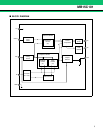
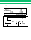
■ FUNCTIONAL DESCRIPTIONS
Two different frequencies can be selected by Div input “H” or “L”.
The divide ratios are calculated using the following equation:
f
VCO = {(P × N) + A} × fOSC ÷ R (A < N)
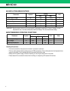
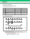
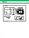
■ PHASE DETECTOR TIME CHART
Note: • .Phase error detection range: –2π to +2π
• Pulses on Do output signal during locked state are output to prevent dead zone.
• LD output becomes low when phase is t
WU or more. LD output becomes high when phase error is tWL or
less and continues to be so for three cycles or more.
•.t
WU and tWL depend on OSCin input frequency.
t
WU > 8/fosc (s) (e. g.tWU > 625.0ns, foscin = 12.8 MHz)
tWL < 16/fosc (s) (e. g. tWL < 1250.0ns, foscin = 12.8 MHz)
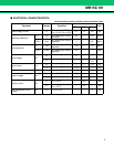
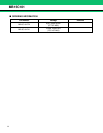
Symbol Description Div = “H” Div = “L”
fvco Output frequency of external VCO 233.15 MHz 259.20 MHz
fosc Reference oscillation frequency 19.2 MHz 19.2 MHz
N Divide ratio of the main counter 291 33
A Divide ratio of the swallow counter 7 12
P
Preset divide ratio of dual modulus
prescaler
16/17 16/17
R Divide ratio of the reference counter 384 (fr = 50 kHz) 40 (fr = 480 kHz)
fr
fp
LD
D
O High impedance
t
WLtWU