


F
F
u
u
j
j
i
i
t
t
s
s
u
u
P
P
L
L
L
L
F
F
r
r
e
e
q
q
u
u
e
e
n
n
c
c
y
y
S
S
y
y
n
n
t
t
h
h
e
e
s
s
i
i
z
z
e
e
r
r
I
I
C
C
s
s
M
M
B
B
1
1
5
5
0
0
0
0
E
E
B
B
2
2
0
0
B
B
E
E
v
v
a
a
l
l
u
u
a
a
t
t
i
i
o
o
n
n
B
B
o
o
a
a
r
r
d
d
M
M
a
a
n
n
u
u
a
a
l
l
2003.Feb.Rev0.1
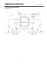
1.0 General Description
The MB1500EB20B is the evaluation board for MB15F7xUV and MB15F3xUV in BCC package. You
can evaluate almost performance of PLL by this evaluation board.
MB15F7xUV and MB15F3xUV integrate RF and IF PLL. When evaluating the devices, you can
measure the RF/IF loop characteristics by putting the RF/IF VCO and RF/IF loop filter on the board.
Each output pad for RF/IF VCO output and the external input for REF, CLK, Data, LE are prepared on
the board. Thus it is easy to connect their input/output. RF/IF VCO and RF/IF loop filter are not help
you on the board, so you can mount whatever you want.
Regarding CLK, Data and LE input, Fujitsu prepare the software and the cable. The sets can control
the data on a PC easily. (The part number of the cable is MB1500EB00A)
The socket for IC is set on the board, by which you can try evaluating many samples.
2.0
Design Kit
The design kit includes the following items.
-Evaluation board with the socket for BCC package.
-Evaluation board manual
3.0
Set up
1.VCO and Loop filter
RF/IF VCO and RF/IF PLL are not mounted on the board. You can mount whatever you want.
2.REFin
Connect a signal generator or TCXO to the REF pad. If the TCXO module is used, remove the
51ohm resistor.
3.VCO output
Connect RFVCO output pad to the spectrum analyzer or the modulation domain analyzer.
*SMA connector does not connect to IF VCO output pad.
4.CLK, Data, LE
Connect the output pin of printer port or the special cable through a PC to the pins of CLK,
Data and LE.
Fujitsu prepare the special cable for the Fujitsu’s software of writing data.
The part number is MB1500EB00A. If you need it, please contact the sales.
5.Vcc and Vp
Connect a DC power supply output to the Vcc and Vp pins.
VccRF and VccIF must supply equal voltage. Even if RF-PLL or IF-PLL is not used, the equal
level of power must be supplied to VccRF and VccIF. When you don’t need both of RF/IF PLLs,
it recommend the non-use PLL is controlled by power saving function.
6.PLL IC
The socket is attached on the board. It helps you to measure many PLL samples.
.
7.Power saving switch
There are two switches. You can control the power saving mode by them. RF and IF are separated.
- 3 -