HDS-16/HRM-16 HEADPHONE DISTRIBUTION SYSTEM
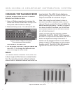
Note: The remote and front panel switches
are wired in parallel. Although either switch
can activate the SOLO function, both must
be in the off position to deactivate it.
REAR PANEL
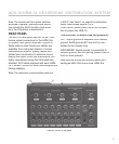
The HDS-16 rear panel has six, 50-pin, Cen-
tronics output connectors for the HRM-16s,
AC-power, and ground switches (Figure 5).
While male-to-male Centronics cables are
available from computer re tail ers, Furman
manufactures superior quality cables with
twisted pair con struction to optimize sound
quality and reject cross-talk interference. We
highly recommend using the 25 twisted pair,
shielded, 25-ft cable supplied with each HRM-
16. Contact Furman for other cable lengths and
linking adapt ers.
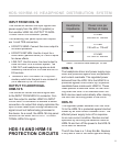
Note: The maximum recommended cable run
is 200 ft. See Table 1 on page 8 for information
about cable losses beyond 100 ft.
Push the AC-power switch up to the ON posi-
tion to power the HDS-16.
The GROUND lift switch has two positions:
LIFT: Signal ground is separate from chassis
ground. Earth ground (AC line cord) is con-
nected to the chassis only.
GROUNDED: Signal ground is connected to
chassis ground; use this setting unless there is
hum or noise present.
Note: Be sure all units are turned off before con-
necting an HDS-16 to one or more HRM-16’s.
6
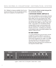
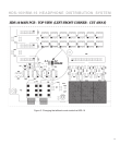
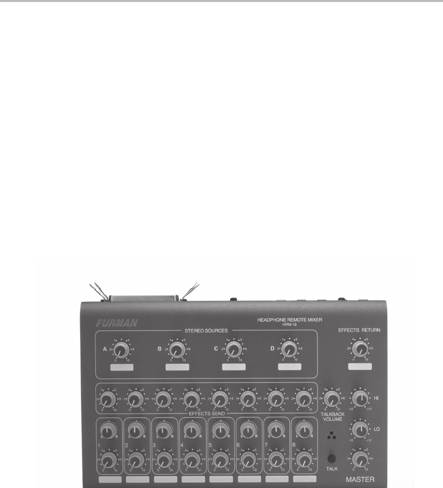
Figure 6: HRM-16 top panel


