


Page 4
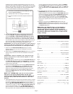
is identical to the crossfader supplied with the mixer) has a 45 mm
travel from side to side. Part # RF-30 is available with a 30 mm travel
distance. Also available is the PSF-45 with a special curve designed
for scratch mixing. Just purchase one of these crossfader units
from your Gemini dealer and follow these instructions:
1. Unscrew the outside FADER PLATE SCREWS (B). Do not
touch the INSIDE SCREWS (C).
2. Carefully lift the fader and unplug the CABLE (D).
3. Plug the new fader into the cable and place it back in the
mixer.
4. Screw the fader to the mixer.
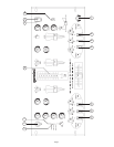
6. KILLING FREQUENCIES: There are two ways to kill frequencies,
using the LOW, MID and HIGH KILL SWITCHES (22, 23, 24) and
using the LOW, MID and HIGH ROTARY CONTROLS (18, 19, 20).
When the selected KILL SWITCH is activated the LED will light and
the frequency will be killed. When the selected ROTARY CONTROL
is turned all the way to the left, the frequency will be killed. You can
also use the ROTARY CONTROLS to boost frequencies up to +12
dB. The normal setting for the ROTARY CONTROLS is zero.
SUGGESTION: You can use the Kill Features on each channel to
remove Low, Mid and/or High bands for a smoother mix and to
mix frequencies from both channels to create special effects.
7. PUNCH IN: The PUNCH IN BUTTON (25) allows you to add a
channel’s signal to the mix when the crossfader is set to the
opposite channel.
8. PUNCH OUT: The PUNCH OUT BUTTON (26) allows you to remove a
channel’s signal from the mix when the crossfader is set to that
channel.
SUGGESTION: Keep the crossfader in the center and use the
punch in and punch out of both channels together to create
scratch type effects.
9. LOOP SECTION: To activate loop, press the LOOP BUTTON (27) and
the LOOP LED (28) will light. When the LOOP LED is lit, any device
connected to the LOOP OUTPUT (43) and INPUT (44) jacks will be
inserted into the signal path.
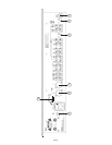
10. OUTPUT CONTROL SECTION: The level of the AMP OUT (39, 40) is
controlled by the MASTER (29) slide. The BOOTH (30) control
adjusts the level of the BOOTH OUTPUT (41). HINT: The booth
OUTPUT is used by some DJs to run monitor speakers in their DJ
booth. You can also use it as a second ZONE or AMP output.
Activating the MONO (37) button (the mono LED will light) makes the
overall output mono.
NOTE: The RECORD OUT (42) has no level control.
The level is set by the channel slides and the gain
controls of the selected channel. The tonal qualities are
set by the bass, treble and mid controls of that same
channel.
11. TALKOVER SECTION: The purpose of the talkover section is to allow
the program playing to be muted so that the mic can be heard above
the music. The MIC/TALKOVER SWITCH (4) has three settings.
When the MIC/TALKOVER SWITCH (4) is in the bottom position, MIC
I and talkover are both off. When the MIC/TALKOVER SWITCH (4)
is in the center position MIC I is on, the MIC INDICATOR (5) will
glow, but talkover is off. When the MIC/TALKOVER SWITCH (4) is
in the top position, MIC I and talkover will be on and the volume of all
sources except the Mic inputs are lowered by 16 dB. The TREBLE
(7) and BASS (8) controls allow you to fully adjust the tone of MIC I
and MIC II. MIC I LEVEL (9) controls the level of MIC I. The MIC II (6)
button activates MIC II and the MIC II LEVEL (10) controls the level
of MIC II.
12. CUE SECTION: By connecting a set of headphones to the
HEADPHONE (11) jack, you can monitor either channel or both
together. Select the Channel I by sliding the CUE SLIDER (32) control
to the left or Channel II by sliding the CUE SLIDER (32) control to the
right. Use the CUE LEVEL (33) control to adjust the headphone
volume without effecting the overall mix. Use the CUE SPLIT (34)
button to split the signals from each channel so that channel I will be
heard in one earphone and channel II will be heard in the other
earphone.
13. DISPLAY: The dual function DISPLAY (35) indicates either the
MASTER OUTPUT (39, 40) left and right levels or the channel I and
channel II levels. You can choose the option you want by pressing
the DISPLAY (36) button.
NOTE: When the DISPLAY (35) is in the channel I/
channel II display mode, by adjusting the individual
channel gain and tone controls, you can increase or
decrease the signal to match the other channels signal.
The channel slides and crossfader have no effect on the
display readings.
Specifications
INPUTS:
DJ Mic....................................................1.5mV 2Kohm balanced
Phono.........................................................................3mV 47Kohm
Line.......................................................................150 mV 27Kohm
Aux.......................................................................150 mV 27Kohm
OUTPUTS:
Amp/Booth......................................................0 dB 1V 400ohm
Max..............................24V Peak to Peak
Rec...........................................................................225mV 5Kohm
MICs:
Bass......................................................................................± 12dB
High.......................................................................................± 12dB
GENERAL:
Bass (Chnls I - II).......................................................+ 12dB/Kill
Mid (Chnls I - II)..........................................................+ 12dB/Kill
Treble (Chnls I - II).....................................................+ 12dB/Kill
Gain (Chnls I - II)..............................................................0 to -20dB
Frequency Response....................................20Hz - 20KHz +/- 2dB
Distortion................................................................................0.02%
S/N Ratio...............................................................better than 80dB
Talkover Attenuation..............................................................-16dB
Headphone Impedance.........................................................16ohm
Power Source.............................................115/230V 50/60Hz 10W
Dimensions...........................................19”w x 3 1/2”h x 8”d
Weight........................................................................10 lbs