


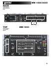
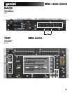
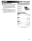
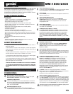

CONTROLS:
18
20
21
MICROPHONE VOLUME
Plug your main MIC into the MIC 1 combination
XLR-1/4" input located on the face panel. The rotary controls for. The
rotary MIC 1 VOLUME CONTROL, above the rotary MIC 2 VOLUME
CONTROL, adjusts the decibel level of MIC 1. You may also plug a
second & third MIC into the rear panel's MIC 2 & MIC 3 1/4" jacks.
The decibel level of MIC 2 is controlled by the rotary MIC 2 VOLUME
CONTROL. The decibel level of MIC 3 is controlled by the CH 1
SLIDE CONTROL.
MICROPHONE EQ and TALKOVER SWITCH
The MICROPHONE EQ Let’s you to control the low frequency and
the high frequency of the microphone signal. The TALKOVER switch
allows you to quickly attenuate the main output so the microphone
can be heard over the main music program.
EQUALIZER (EQ)
These units feature dual 10 BAND GRAPHIC EQUALIZER that will
allow you to adjust the sound to fit any room. By adjusting any of the
10 EQ SLIDE CONTROLS, you can cut or boost the tonal characteris-
tics of the sound coming from PGM to the speaker(s) by ±12 dB.
EQ SWITCH
To activate the dual 10 BAND GRAPHIC EQ, switch the EQ SWITCH
to ON, & the EQ LED will light up to indicate that the EQ has been
engaged. To deactivate the dual 10 band graphic EQ, switch the EQ
SWITCH to OFF, & the EQ LED will turn OFF. When activated, the
EQ controls the LEFT and RIGHT side of your stereo speakers. The
PGM & EQ are controlled by the MASTER VOLUME. To balance the
sound of the PGM playing through the MASTER VOLUME on the
LEFT & RIGHT side of your speakers you must mirror the EQ levels
on the LEFT & RIGHT EQ controls.
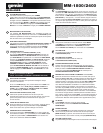
MIXER CHANNEL
(NOTE: ALL 4 CHANNELS HAVE THE SAME FEATURES)
CHANNEL INPUT SELECTOR
The CHANNEL INPUT SELECTOR switches allow you to choose
which input will be controlled by that channels corresponding
volume FADER.
For example on CHANNEL (1) the INPUT SELECTOR allows you to
choose between LINE 1 and MIC 3 , on CHANNEL (2) the
INPUT SELECTOR SWITCH will let you choose between PHONO
1/LINE 2 and LINE 3 and on CHANNEL (3) you can choose between
PHONO 2/LINE 4 and the LINE 5 input, and on CHANNEL (4) you
can choose between LINE 6 and LINE 7.
CHANNEL CUE SELECTOR SWITCH
The CHANNEL CUE SELECTOR SWITCH allows you to choose
which channel you wish to monitor in your headphones by pressing
this switch on any channel you will be able to listen to that channels
input in your headphones multiple CHANNEL SWITCHES can be
pressed to monitor more than on input at a a time.
CHANNEL VOLUME FADER
After you have chosen which input you will use with the INPUT
SELECTOR the corresponding CHANNEL FADER will allow you to
adjust the volume for that particular CHANNEL.
CROSSFADER ASSIGNMENT
The fader assignment rotary allows you to assign which two of the 4
channels will be controlled by the CROSSFADER.There are 5
selections for either side of the CROSSFADER which can be either
CHANNEL 1,2,3,4 or OFF, In the OFF position the CROSSFADER
will not affect the volume of any CHANNEL.
6
14
15
16
17
19
22
1923
MM-1800/2400
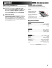
CROSS FADER
The CROSS FADER allows you to mix evenly from one source to an-
other. On the MM-1800/2400 The CROSSFADER is assignable be-
tween either channels (1) and (2) or channels (3) and (4) depending
on the position of the fader assignment push button (see above).
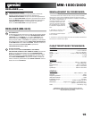
The CROSS FADER on the MM-1800/2400 is also removable and if
the need arises can be replaced.The RG-45 (RAILGLIDE™)
DUAL-RAIL CROSS FADER, which has internal dual stainless steel
rails that allow the slider to ride smoothly and accurately from end to
end can be purchased from your local GEMINI dealer.
NOTE: FOR OPTIMAL PERFORMANCE IN YOUR SOUND OUTPUT, HAVE YOUR SOUND
SET TO STEREO NOT MONO. START WITH THE EQ LEVELS AT CENTER VALUE. THE EQ SLIDE CON-
TROLS SHOULD LOCK AT THIS POSITION. ADJUST YOUR MASTER VOLUME CONTROL FROM MID TO
LOW VOLUME RANGE. THEN ADJUST THE LEFT OR RIGHT EQ, ONE SLIDE CONTROL AT A TIME, TO A
COMFORT ABLE LEVEL. ONCE YOU ARE SATISFIED WITH THE SOUND OF ONE SIDE, MATCH THE EQ
SETTINGS ON THE OTHER SIDE. ONCE YOU HAVE PASSED THE CENTER VALUE ON THE EQ, THE
MASTER OUTPUT, AS INDICATED IN THE VU METER MAY EXPERIENCE A TONAL BOOST. PLEASE AD-
JUST THE MASTER VOLUME TO A COMFORTABLE LEVEL SO YOU DO NOT OVERLOAD YOUR SYS-
TEM. CLIPPING WILL OCCUR WHEN YOU ARE OVERLOADING YOUR SYSTEM. LOWER THE MASTER
VOLUME OR ADJUST YOUR EQ SETTINGS SO THAT CLIPPING DOES NOT OCCUR. THEN YOU MAY
RAISE THE MASTER VOLUME TO A LEVEL WITH WHICH YOU ARE COMFORTABLE.
STEREO/MONO SWITCH
You can convert your sound output from STEREO to MONO & vice
versa by using the STEREO/MONO SWITCH. Switch to the LEFT to
convert to STEREO. Switch RIGHT to convert to MONO.
ZONE VOLUME ROTARY
Controls the volume level of the ZONE OUTPUT.
BOOTH VOLUME ROTARY
Controls the volume level of the BOOTH OUTPUT.
MASTER VOLUME CONTROL
Once you are comfortable with the sound level of your music you
may adjust the decibel level of the PGM with the MASTER VOLUME
CONTROL. MASTER RCA & BALANCED MASTER OUTPUTS are
controlled by the level of the MASTER VOLUME control.
BNC LAMP PORT
The BNC LAMP PORT connects a 12 V BNC goose neck lamp, such
as the Gemini GNL-700 to the mixer.The goose neck lamp will be
powered by your mixer. To turn ON the goose neck lamp, you must
first attach the goose neck lamp to the BNC LAMP PORT. Make sure
the mixer is OFF when connecting the 12 V BNC lamp. To connect
the goose neck lamp, simply align the screw cap of the goose neck
lamp to the locking nodules of the BNC LAMP PORT, push down, &
twist the screw cap clockwise to lock the 12 V BNC goose neck lamp
in place. Then turn ON your mixer. The goose neck lamp should
light-up. To detach the goose neck lamp from the BNC LAMP PORT,
first make sure your mixer is OFF. Turn OFF your mixer and the
goose neck lamp will turn OFF. Unscrew the screw cap by twisting it
counterclockwise, then pull up & remove the goose neck lamp.
VU METER
The VU METER indicates the decibel level of the MASTER RCA &
MASTER BALANCED outputs of the LEFT & RIGHT stereo levels.
CUE/PGM FADER
The CUE/PGM FADER determines the mix between the chosen
CHANNEL CUE SELECTION and the MAIN OUTPUT mix.
To the left is the CUE program and to the right is MAIN OUTPUT.
CUE VOLUME ROTARY KNOB
The CUE VOLUME ROTARY KNOB adjusts your HEADPHONE
MONITOR OUTPUT volume.
POWER SWITCH
Once all of your connections have been made in the rear panel,
turn ON the mixer by pressing the POWER SWITCH. Once turned
ON, the POWER BAR LED, containing the power symbol located in
the VU METER, will be illuminated. Turn OFF the mixer when not in
use by pressing the POWER SWITCH to OFF. When the mixer is
turned OFF the POWER BAR LED will not be illuminated.
1924
1925
1926
1927
1928
1929
1930
1931