


also plug a second & third MIC into the rear panel's MIC 2 (20) & MIC 3
(19) 1/4" jacks. The decibel level of MIC 2 (20) is controlled by the rotary
MIC 2 VOLUME CONTROL (51). The decibel level of MIC 3 (19) is con-
trolled by the CH 1 SLIDE CONTROL (39).
13. TALKOVER: The purpose of the AUTO TALKOVER MODE is to
allow the program playing to be attenuated so that the MIC may be
heard above the music. The AUTO TALKOVER SWITCH (54) controls
MIC 1 (49) and MIC 2 (20) with 3 settings:
- When the MIC/TALKOVER SWITCH (54) is in the BOTTOM position,
MIC 1 (49), MIC 2 (20) & TALKOVER MODE are all OFF.
- When the MIC/TALKOVER SWITCH (54) is in the CENTER position,
MIC 1 (49) & MIC 2 (20) are ON & TALKOVER MODE is OFF. The MIC
ON LED indicator glows when MIC 1 (49) & MIC 2 (20) are ON.
- When the MIC/TALKOVER SWITCH (54) is in the TOP position, MIC
1 (49) & MIC 2 (20) are ON, TALKOVER MODE is ON, & the volume of
all sources except MIC 1 (49) & MIC 2 (20) are lowered automatically by
-16 dB, when speaking into the MIC(s).
14. BNC LAMP PORT: The BNC LAMP PORT (22) connects a 12 V
BNC
goose neck lamp, such as the Gemini GNL-700 to the PDM mixer.
The goose neck lamp will be powered by your mixer. To turn ON the
goose neck lamp, you must first attach the goose neck lamp to the BNC
LAMP PORT (22). Make sure the PDM mixer is OFF when connecting
the 12 V BNC lamp. To connect the goose neck lamp, simply align the
screw cap of the goose neck lamp to the locking nodules of the BNC
LAMP PORT (22), push down, & twist the screw cap clockwise to lock
the 12 V BNC goose neck lamp in place. Then turn ON your mixer. The
goose neck lamp should light-up. To detach the goose neck lamp from
the BNC LAMP PORT (22), first make sure your mixer is OFF. Turn OFF
your mixer and the goose neck lamp will turn OFF. Unscrew the screw
cap by twisting it counterclockwise, then pull up & remove the goose
neck lamp.
15. GROUND LIFT SWITCH: The GROUND LIFT SWITCH (8) is used
to reduce background noise & hum when using multiple outlets to power
audio equipment. The switch should be in the position that provides the
least amount of noise or hum. If noise remains at the same level in both
positions, the GROUND LIFT SWITCH (8) should be kept in the GND
position.
NOTE: MAKE SURE THE MIXER AND/OR AMPLIFIER IS OFF BEFORE SWITCHING THE
GROUND LIFT SWITCH TO PREVENT ATRANSIENT POP THAT MAY DAMAGE YOUR SYS-
TEM.
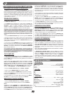
16. VU METER: The VU METER (23) indicates the decibel level of the
MASTER RCA & MASTER BALANCED (3 & 6) outputs of the LEFT &
RIGHT stereo levels.
ECHO SECTION:
An echo effect may be applied to the PGM, or MIC 1 (49) & MIC 2 (20)
signals by switching the ECHO ASSIGN (55) switch from MIC 1-2 on the
LEFT, to OFF in the MIDDLE, to MASTER on the RIGHT & vice versa.
When using ECHO (55), you may adjust the effect of the ECHO (55) by
using the rotary REPEAT (56), DELAY (57), and ECHO VOLUME (58)
controls. To turn the ECHO ASSIGN (55) OFF or lower the ECHO VOL-
UME (58).
SOUND EFFECTS SECTION:
Six different sound effects (APPLAUSE, SCREAM, COPTER,
SCRATCH, H
2
O & GLASS) may be added to your mix by pressing the
SOUND EFFECTS CONTROL BUTTONS (61). The volume of the
effects can be adjusted using the rotary EFX VOLUME (60) located
above the APPLAUSE effect button. The pitch of the effects can be
increased or decreased using the rotary SPEED CONTROL (59) locat-
ed above the SCRATCH effect button.
MEMORY INFORMATION:
The PDM-03 is equipped with 5 MEMORY BANKS (59). The two banks
marked 8 & 8 are 8 seconds in length, the two banks marked 16 & 16
are 16 seconds in length and the bank marked 48 is 48 seconds in
length. These banks are separate & CANNOT be linked. You can store
a different sample in each bank, but they must be recorded individually
& must be played one at a time.
(77)
ASSIGN switch allows you to direct CH 1, 2, 3, or 4 through the LEFT
side of the CROSS FADER (36). The RIGHT ASSIGN (35) switch allows
you to direct CH 1, 2, 3, or 4 through the RIGHT side of the CROSS
FADER (36). When the ASSIGN SWITCH(es) (34, 35) are at OFF, you
will not have a CH assigned to the CROSS FADER (36). This allows you
to control the PGM with the use of the respective CH SLIDE CON-
TROLS, thus layering the PGM with up to four CHs.
8. CROSS FADER SECTION: The CROSS FADER (36) allows you to
mix from one source to another. The PDM mixers feature an assignable
CROSS FADER (36). The rotary controlled ASSIGN SWITCHES (34,
35) allow you to select which channel will play through each side of the
CROSS FADER (36). The CROSS FADER (36) in your unit is remov-
able & if the need arises can be easily replaced. Your Gemini mixer
comes with a RG- 45 (RAILGLIDE™) DUAL-RAIL CROSS FADER.
RAIL GLIDE™ CROSS FADERS have internal dual stainless steel rails
that allow the slider to ride smoothly and accurately from end to end.
Also available is our RG-45 PRO (PROGLIDE™) CROSS FADER with
a special curve designed for scratch mixing. Just purchase one from
your Gemini dealer & follow the instructions:
NOTE: DO NOT APPLY PRESSURE WHILE USING THE CROSSFADER. LIGHTLY GLIDE
THE CROSSFADER BACK AND FORTH. PRESSING DOWN ON THE CONTROLS CAN
BEND CONTACTS AND CAUSE A LOSS OF SOUND.
9. EQUALIZER (EQ): These units feature dual 10 BAND GRAPHIC
EQUALIZERS (32, 33) that will allow you to adjust the sound to fit any
room. By adjusting any of the 10 EQ SLIDE CONTROLS (32, 33), you
can cut or boost the tonal characteristics of the sound coming from PGM
to the speaker(s) by ±12 dB. To activate the dual 10 BAND GRAPHIC
EQ, switch the EQ SWITCH (31) to ON, & the EQ LED will light up to
indicate that the EQ has been engaged. To deactivate the dual 10 band
graphic EQ, switch the EQ SWITCH (31) to OFF, & the EQ LED will turn
OFF. When activated, the EQ (32, 33) controls the LEFT and RIGHT
side of your stereo speakers. The PGM & EQ are controlled by the MAS-
TER VOLUME (27). To balance the sound of the PGM playing through
the MASTER VOLUME (27) on the LEFT & RIGHT side of your speak-
ers you must mirror the EQ levels on the LEFT (32) & RIGHT (33) EQ
controls.
NOTE: FOR OPTIMAL PERFORMANCE IN YOUR SOUND OUTPUT, HAVE YOUR SOUND
SET TO STEREO NOT MONO. START WITH THE EQ LEVELS (32, 33) AT CENTER VALUE.
THE EQ SLIDE CONTROLS (32, 33) SHOULD LOCK AT THIS POSITION. ADJUST YOUR
MASTER VOLUME (27) CONTROL FROM MID TO LOW VOLUME RANGE. THEN ADJUST
THE LEFT (32) OR RIGHT (33) EQ, ONE SLIDE CONTROL AT A TIME, TO A COMFORT
ABLE LEVEL. ONCE YOU ARE SATISFIED WITH THE SOUND OF ONE SIDE, MATCH THE
EQ SETTINGS ON THE OTHER SIDE. ONCE YOU HAVE PASSED THE CENTER VALUE ON
THE EQ (32, 33), THE MASTER OUTPUT, AS INDICATED IN THE VU METER (23), MAY
EXPERIENCE ATONAL BOOST. PLEASE ADJUST THE MASTER VOLUME (27) TO ACOM-
FORTABLE LEVELSO YOU DO NOT OVERLOAD YOUR SYSTEM. CLIPPING WILL OCCUR
WHEN YOU ARE OVERLOADING YOUR SYSTEM. LOWER THE MASTER VOLUME (27) OR
ADJUST YOUR EQ (32, 33) SETTINGS SO THAT CLIPPING DOES NOT OCCUR. THEN YOU
MAY RAISE THE MASTER VOLUME (27) TO A LEVEL WITH WHICH YOU ARE COMFORT-
ABLE.
10. STEREO/MONO: You can convert your sound output from STEREO
to MONO & vice versa by using the STEREO/MONO SWITCH (30).
Switch to the LEFT to convert to STEREO. Switch RIGHT to convert to
MONO.
11. OUTPUT SELECTION CONTROL: Once you are comfortable with
the sound level of your music you may adjust the decibel level of the
PGM with the MASTER VOLUME (27) control. MASTER RCA & BAL-
ANCED MASTER OUTPUTS (3, 6) are controlled by the level of the
MASTER VOLUME (27) control. You may adjust the volume of the
ZONE (5) output with the ZONE (29) rotary control. You may adjust the
volume of the BOOTH (7) output with the BOOTH (28) rotary control.
The volume of your RECORD (4) output is controlled strictly by the CH
SLIDE CONTROLS.
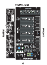
12. MIC SECTION: Plug your main MIC into the MIC 1 combination
XLR-1/4" input (49) located on the face panel. The rotary controls for
HIGH (52) and LOW (53) allow you to adjust the tone of MIC 1 (49). The
rotary MIC 1 VOLUME CONTROL (50), above the rotary MIC 2 VOL-
UME CONTROL (51), adjusts the decibel level of MIC 1 (49). You may
PPDDMM
SSEERRIIEESS
PPDDMM
SSEERRIIEESS
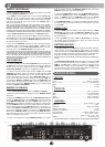
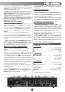
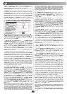
REPLACEABLE CROSS FADER
1. UNSCREW THE OUTSIDE
FADER PLATE SCREWS (B).
- DO NOT TOUCH INSIDE
SCREWS (C).
2. CAREFULLY REMOVE OLD
CROSS FADER AND UNPLUG
CABLE (D).
3. PLUG IN THE NEW CROSS
FADER INTO CABLE (D) AND
PLACE BACK INTO MIXER.
4. SCREW THE CROSS FADER
TO MIXER WITH THE FADER
PLATE SCREWS (B).
PDM-02 ECHO/EFX:
PDM-03 SAMPLER OPERATION: