


Page 5
)
)
NOTE: When the DISPLAY (28) is in the channel 2/channel
3 display mode, by adjusting the indivldual channel gain
and tone controls, you can increase or decrease the
signal to match the other channel’s signal. The channel
slides and crossfader have no effect on the display
readings.
11. The CROSSFADER CURVE SWITCH (42) allows you to adjust the
kind of curve the crossfader has, Move switch to the “sharp” position to
make the curve steep and cutting (perfect for scratching ). Move switch
to the “gradual” position to make the curve gradual and gentle. The
CROSSFADER REVERSE SWITCH (43) allows you to reverse the
crossfader so that CHANNEL 3 is controlled by the left side of the
crossfader and CHANNEL 2 is controlled by the right side of the
crossfader.
NOTE: When the CROSSFADER REVERSE SWITCH (32) is
activated, only the crossfader reverses. The Channel
Slides, Gain, and Tonal controls do not reverse.
)
)
✦
Your Gemini mixer comes with an
RG-45 PRO (RAIL
GLIDE™) DUAL-RAIL CROSSFADER
. Rail Glide™
Crossfaders have internal dual stainless steel rails that allow the
slider to ride smoothly and accurately from end to end.
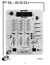
4. CROSSFADER SECTION: The CROSSFADER (26) allows the mixing
of one source into another. The left side of the CROSSFADER (26) is
channel 2 and the right side is channel 3.
5. BPM DISPLAY: There are BPM DISPLAYS(23,24) for Channel 2 and
Channel 3. They update approximately every 2.5 seconds and
digitally display the Beats Per Minute allowing you to match the beats
visually. BPM DISPLAY(23) reflects the Beats Per Minute of Channel
2, and BPM DISPLAY(24) reflects the Beats Per Minute of Channel 3.
NOTE: A [- -]reading will appear on the BPM DISPLAY if
the track has unclear beats. The [- -]reading will also
appear if there is no signal present.
6. The BEAT OFFSET INDICATORS (25) light when the tracks of
Channel 2 and Channel 3 are within 11 BPMs of each other and
display how aligned the beats for Channel 2 and Channel 3 are.
When the RED LEDs light, the beats are not aligned. When the
YELLOW LEDs light, the beats are almost aligned. When the GREEN
LED lights, the beats are aligned perfectly.
NOTE: If the difference between the two channel’s
beats exceed 11 BPM, the BEAT OFFSET INDICATORS will
not light.
SUGGESTION: You can use the BPM DISPLAYS to determine
which tracks have similar or the same Beats Per Minute. When
mixing two tracks with similar Beats Per Minute, you can use
one source’s pitch control to align the Beats Per Minute with the
other source’s BPM. The BPM DISPLAYS and the BEAT OFFSET
INDICATORS update every 2.5 seconds and will reflect the
change in BPM and indicate when the beats are aligned.
NOTE: Beat mixing is a skill that requires practice. Not
every track has a strong beat, and beat mixing works
best with tracks with clear and strong beats.
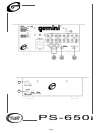
7. OUTPUT CONTROL SECTION: The level of the AMP OUT (38) is
controlled by the MASTER (18) control. The BALANCE (17) control
will allow the Amp Out signal to be balanced between the left and
right speakers. The BOOTH (16) control adjusts the level of the
BOOTH OUTPUT (39).
HINT: BOOTH OUTPUT (39) is used by some DJs to run monitor
speakers in the DJ Booth. You can also use it as a second
ZONE or AMP output.
NOTE: The RECORD OUT (40) has no level control. The level is
set by the channel slides and the gain controls of the selected
channel. Tonal qualities are set by the low, mid and high
controls of that same channel.
8. TALKOVER SECTION: The purpose of the talkover section is to allow
the program playing to be muted so that the mic can be heard above
the music. When the TALKOVER (19) button is pushed, the
TALKOVER INDICATOR (28) will glow and the volume of all sources
except the Mic or whatever is connected to the PHONO/LINE (36)
input are reduced by 16 dB.
9. CUE SECTION: By connecting a set of headphones to the
HEADPHONE (4) jack, you can monitor any or all of the channels.
Select the correct CUE (21) button or buttons and their respective
CUE LED (5) indicators will glow. Use the CUE LEVEL (20) control to
adjust the headphone volume without effecting the overall mix. By
sliding the CUE PGM PAN (22) control to the left you will be able to
monitor the assigned cue signal. Sliding to the right will monitor the
PGM (program) output.
10. DISPLAY: The peak hold, dual function DISPLAY(27) indicates either
the MASTER(38) output left and right levels or the channel 2 and
channel 3 levels. You can choose the option you want by pressing
the DISPLAY(28) button.