


Page 3
INTRODUCTION
Congratulations on purchasing a Gemini Platinum Series model PS-767
mixer. This state of the art mixer includes the latest features backed by a
three year warranty. Prior to use, we suggest that you carefully read all the
instructions.
FEATURES
• 4 Stereo channels (2 Phono/6 Line)
• 1 DJ Mic channel
• 1 Aux Mic or Line Mono channel
• Combo XLR or 1/4" DJ Mic jack
• Bass, Mid, Treble and Gain controls on each channel
• The DJ Mic and Aux channels have pan controls
• Assignable, removable crossfader
• Assignable Beat indicators
• Assignable Send plus Receive effects circuitry for adding off board
sound enhancers such as digital samplers
• DJ Mic loop
• 6 Drum sound effects
• Echo section assignable to Mic or Music with appropriate delay times for
each source
WORDS TO THE WISE
1. All operating instructions should be read before using this equipment.
2. To reduce the risk of electrical shock, do not open the unit. There are
NO USER REPLACEABLE PARTS INSIDE. Please refer servicing to a
qualified service technician.
3. Do not expose this unit to direct sunlight or to a heat source such as a
radiator or stove.
4. This unit should be cleaned only with a damp cloth. Avoid solvents or
other cleaning detergents.
5. When moving this equipment, it should be placed in its original carton
and packaging. This will reduce the risk of damage during transit.
CAUTIONS
DO NOT EXPOSE THIS UNIT TO RAIN OR MOISTURE.
DO NOT USE ANY SPRAY CLEANER OR LUBRICANT ON ANY
CONTROLS OR SWITCHES.
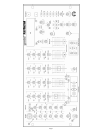
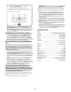
CONNECTIONS
1. Before plugging in the power cord, make sure that the VOLTAGE
SELECTOR (65) switch is set to the correct voltage.
Note: This product is double insulated and not intended to be
grounded.
2. Make sure that the POWER (1) switch is in the off position. The
POWER LED (2) will be off.
3. The PS-767 is supplied with 3 sets of output jacks. The OUTPUT AMP
(66) jacks are used to connect to your main amplifier. The OUTPUT
REC (67) jacks can be used to connect the mixer to the record input of
your recorder enabling you to record your mix. The OUTPUT BOOTH
(68) jacks allow you to hook up an additional amplifier.
4. The PS-767 is equipped with 2 microphone inputs. The DJ MIC (3) input
(found on the front panel) accepts 1/4" or XLR connectors and suitable
for balanced or unbalanced microphones. The AUX MIC (69) input (found
on the rear panel) is a 1/4" jack for an unbalanced microphone.
5. On the rear panel are 2 stereo PHONO (70, 71) inputs, 6 stereo LINE
(72, 73, 74, 75, 76, 77) inputs and 1 mono AUX LINE (78) input. The
stereo phono inputs will accept only turntables with a magnetic cartridge.
A GROUND (79) screw for you to ground your turntables is located on
the rear panel. The stereo line inputs will accept any line level input such
as a CD player, a cassette player, etc.
Note: The AUX LINE (78) input is composed of 2 RCA jacks.
When connecting a mono line level source, either jack can be
used. By connecting a stereo line level device to both jacks, the
input will be combined to one mono signal.
6. Headphones can be plugged into the front panel mounted HEADPHONE
(4) jack.
7. The PS-767 comes with a front panel XLR LIGHT (5) jack. This jack is
for use with a gooseneck light like the Gemini GNL-500. NEVER plug a
microphone into this jack.
8. If you are using an off board signal enhancer, you can use the SEND
(80) output to send the signal to the device and the RECEIVE (81) input
jacks to bring the signal back in to the PS-767.
9. The PS-767 is supplied with DJ MIC LOOP (82) jacks that can be used
to add an audio enhancer such as a key controller to the mic circuit..
There must be a connection to these jacks. If no device is being used in
the DJ mic loop, then the jumper wire (included) must be in place.
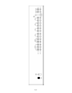
OPERATION
1. POWER ON: Once you have made all the equipment connections to
your mixer, press the POWER SWITCH (1). The power will turn on and
the POWER LED (2) will glow RED.
2. DJ MIC SECTION: The GAIN (6), TREBLE (7), MID (8), BASS (9), PAN
(10) and LEVEL (11) controls allow full adjustment of the DJ mic that is
plugged into the DJ MIC (3) input.
Note: The OVERLOAD LED (12) glows red when the DJ mic is
being over driven. To correct the setting, turn down the GAIN
(6) control until the LED goes off.
3. AUX CHANNEL: By using the AUX MIC/LINE (13) switch, you can
choose between an additional mic or an additional mono line input. The
GAIN (14), TREBLE (15), MID (16), BASS (17), PAN (18) and LEVEL
(19) controls fully adjust the Aux Channel input you selected with the
AUX MIC/LINE (13) switch.
Note: The OVERLOAD LED (20) glows red when the Aux
Channel is being over driven. To correct the setting, turn down
the GAIN (14) control until the LED goes off.
HINT: Like the DJ Mic, the Aux Channel is always live. Hooking up another
mic or a mono line device such as a sound effects generator or a drum
machine, will allow you to play the selected source at any time.
4. MAIN CHANNEL SECTION: To assign an input source to a channel, set
the PHONO/LINE (29,30) and the LINE/LINE (31, 32) switches to their
appropriate positions. To make the proper adjustments to your music,
set the TREBLE (21), MID (22), BASS (23) and GAIN (24) controls and
the CHANNEL (25, 26, 27, 28) slides.
5. CROSSFADER SECTION: The CROSSFADER (38) allows the mixing of
one source into another. The PS-767 features an assignable crossfader.
The ASSIGN (39,43) switches allow you to select which cannel will play
through each side of the CROSSFADER. ASSIGN (39) switch allows
you to select channel 1, 2, 3 or 4 to play through the left side of the
CROSSFADER. ASSIGN (43) switch does the same to the right side of
the CROSSFADER. Each assign switch has its own OFF (40) switch
and OFF INDICATOR (41) LED. With the OFF (40) switch in the off
position (the OFF INDICATOR (41) glows red), that side of the
CROSSFADER (38) will be inactive.
HINT: Try using the OFF (40) switches when you are changing the ASSIGN
(39,43) switch settings. For Example: Assume that you have a turntable
hooked up to channel 1, a tape deck hooked up to channel 2 and a CD
player hooked up to channel 3. The left side ASSIGN (39) switch is set to 1,
the right side ASSIGN (43) is set to 2, and the CROSSFADER (38) is all the
way to the right. Under this set of circumstances, channel 2 will be playing
your tape deck. Now suppose you want to change the left side ASSIGN (39)
switch to # 3 so that you can use your CD player. You must turn the left side
ASSIGN (39) off by pressing the OFF (40) Switch (the OFF INDICATOR
(41) glows red). Then you can make your changes to the setting. Reactivate
the ASSIGN (39) switch by pressing the OFF (40) switch (the OFF
INDICATOR (41) goes off). Failure to do this will result in an audio glitch
when the ASSIGN (39) switch setting is changed.
The CROSSFADER (38) in your unit is REMOVABLE and if the need
arises can be easily replaced. Crossfader units are available in two
sizes. Part # RF-45 (which is identical to the crossfader supplied with the
PS-767) has a 45 mm travel from side to side. Also available is part #
RF-30 which has a 30 mm travel distance Just purchase either of these
crossfader units from your Gemini dealer and follow these instructions: