


Page 4
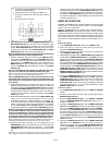
1. Unscrew the outside FADER plate screws (B). Do not
touch the INSIDE SCREWS (C).
2. Carefully lift the fader and unplug the CABLE (D).
3. Plug the new fader into the cable and place it back in
the mixer.
4. Screw the fader to the mixer.
6. BEAT INDICATORS: Each side of the CROSSFADER (38) has its own
BEAT INDICATOR (42, 44). They flash at the low frequency peak
level of each assigned source, allowing you to match the beats
visually. BEAT INDICATOR (42) will reflect the beat of the source
assigned to the left side of the CROSSFADER (38) and BEAT
INDICATOR (44) will do the same for the right side.
Note: The flashing level can be fine tuned by increasing or decreasing
the gain and bass controls of the assigned channel.
7. OUTPUT CONTROL SECTION: The level of the AMP OUT (66) is
controlled by the MASTER (33) slide. The BALANCE (34) control
will allow the Amp Out signal to be balanced between the left and
right speakers. The MONO (35) switch, when depressed, (the
MONO LED (36) will glow), will make the Amp Out signal a mono
signal. The BOOTH (37) control adjusts the level of the BOOTH
OUTPUT (68).
Note: The LED DISPLAY (48) indicates the AMP OUT (66) signal
only and is not affected by the BOOTH OUTPUT (68) signal.
HINT: The booth OUTPUT is used by some DJs to run monitor speakers in their DJ
booth. You can also use it as a second ZONE or AMP output.
Note: The RECORD OUT (67) has no level control. The level is set by
the channel slides and the gain control of the selected channel. The
tonal qualities are set by the bass, treble and mid controls of that
same channel
8. TALKOVER SECTION: The purpose of the talkover section is to
allow the program playing to be muted so that the mic can be heard
above the music. When the TALKOVER ON/OFF (45) button is pushed
(the TALKOVER INDICATOR (46) will glow), the volume of all sources
except the DJ Mic and the Aux channel are reduced. The amount of
reduction can be set between -6 dB and -36 dB by using the MUTE
LEVEL (47) control.
9. SEND AND RECEIVE SECTION: By using the SEND ASSIGN (49)
switch, you can send the selected signal to some sort of audio
enhancement device (like a digital sampler or key controller). The
level of the signal being sent can be adjusted by the SEND (50)
control. To receive the signal back into the PS-924, you must first
turn on the RCV ON (51) switch (LED (52) will light). The level of the
signal being received can be adjusted with the RECEIVE (53) control.
Note: The signal being received back into the PS-924 can be monitored
by using the headphones and by pressing the RECEIVE (54) cue
control. If the RCV ON (51) switch is in the off position (LED (52)
is off), the level of the signal can be monitored and adjusted prior to
its playing through the output. Turning the RCV ON (51) switch to
the on position connects the received signal to the output section.
HINT: The RECEIVE (81) input can be used as an additional stereo line level input
controlled by the RECEIVE (53) and activated by the RCV ON (51) switch.
10.CUE SECTION: By connecting a set of headphones to the
HEADPHONE (4) jack, you can monitor any or all of the channels.
CUE ASSIGN (55) buttons are for the channels 1 - 4 and the CUE
ASSIGN (56) button is for the Aux Mic/Line Mono channel and the DJ
Mic.
HINT: When you are using the DJ Mic and have a device connected to the DJ Mic
Loop, the signal you hear in the headphones includes the device in the loop.
Select the correct Cue assign button or buttons and their respective
LED indicators will glow. Use the HEADPHONE LEVEL (57) control
to adjust the headphone volume with out effecting the overall mix.
By rotating the CUE PGM PAN (58) control to the left you will be able
to monitor the assigned cue signal. Rotating to the right will monitor
the PGM (program) output .
SAMPLER OPERATION
GENERAL INFORMATION: The PS-924 Sampler uses Dynamic RAM
memory and a 12 bit microprocessor controller. The full bandwidth
results in true sound reproduction.
MEMORY INFORMATION: The PS-924 comes equipped with five
MEMORY BANKS (59). The two banks marked 2 & 2 are two seconds
in length, the two banks marked 4 & 4 are four seconds in length and the
bank marked 12 is twelve seconds in length. These banks are separate
and can not be linked. You can store a different sample in each bank but
they must be recorded individually and they must be played one at a
time.
SAMPLE RECORDING:
1. Put the MODE SELECTOR (62) switch into the WRITE position.
2. Select the source you want to sample from by pressing the
appropriate ASSIGN BUTTON (61).
3. Select the memory bank you want to record into, by pressing the
proper MEMORY BANK (59) button.
4. Model PS-924 is equipped with a SAMPLER REC/PLAY LEVEL (63)
control. When the MODE SELECTOR (62) is in the WRITE mode, this
control acts as a Record Level Control. If the OVERLOAD INDICATOR
(62A) is blinking, it means that the input signal you are going to sample, is
too strong and will cause he sample to be distorted. Lower the sample
signal intensity by turning the SAMPLER REC/PLAY LEVEL (63) control
counter clockwise. If the OVERLOAD INDICATOR (62A) is off, turn the
SAMPLER REC/PLAY LEVEL (63) control clockwise until the
OVERLOAD INDICATOR (62A) begins to blink and then turn the
SAMPLER REC/PLAY LEVEL (63) control counter clockwise until the
OVERLOAD INDICATOR (62A) goes off.
5. Tapping the START/STOP (60) button begins the sampling process
(the SAMPLER INDICATOR (60A) will illuminate RED). Tapping the
START/STOP (60) button a second time ends the sample (the
SAMPLER INDICATOR (60A) will turn off). If you do not tap the
START/STOP (60) button a second time, the sampling process will
stop automatically after 2, 4 or 12 seconds depending on which
MEMORY BANK (59) was selected.
SAMPLE PLAYBACK:
1. Put the MODE SELECTOR (62) switch into the SINGLE or REPEAT
position.
2. Select the memory bank you wish to play by pressing the proper
MEMORY BANK (59) button.
3. When the MODE SELECTOR (62) is in the SINGLE or REPEAT
mode, the SAMPLER REC/PLAY LEVEL (63) control acts as a
Sampler Level Control.
4. Tapping the START/STOP (60) button with the MODE SELECTOR
(62) switch in the SINGLE position will cause the sampler to playback
one time (the SAMPLER INDICATOR (60A) will illuminate GREEN).
Every push of the START/STOP (60) button will restart the sample
from the beginning. Rapid pressing of the START/STOP (60) button
will cause a stuttering effect. Once the sample has started playback
and the START/STOP (60) button is not pushed a second time, the
sample will play to the end and then stop (the SAMPLER INDICATOR
(60A) will turn off).
5. Tapping the START/STOP (60) button with the MODE SELECTOR
(62) switch in the REPEAT position will cause the sample to
continuously play over and over (the SAMPLER INDICATOR (60A)
will illuminate GREEN). The START/STOP (60) button will act as an
on/off switch. The first push will start the sample, the second push
will stop it.