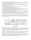
SIGNAL SHAPE – The SHUTTLE MAX 12.0 is equipped with 3 SIGNAL SHAPE circuits, each with a level control to
adjust the amount of level the tone shaping circuit produces.
L.F. BOOST – This lter adds low frequency peaking gain in the 35-65 HZ band range. This is especially effective
when used with a 5 string bass. The level control has a range of 0 to +7dB. This lter is unique in that it provides
compound, asymmetrical slopes critical to achieving well-controlled low frequency extension.
MID SCOOP -- Engaging this switch generates a midrange frequency cut centered at 600 Hz. The level control ad-
justs the amount of cut from 0db to –15dB.
H.F. ATTACK -- adds a peaking high frequency boost in the 2.5K – 16 KHz range. The level control has a range of 0
to +7dB.
LED indicators are provided to visually show when each lter is engaged. Each lter Q (bandwidth) is optimized for
its particular function and is different for each lter. These functions are also foot-switchable from the 5-button foot-
switch.
The switches on the amplier’s faceplate must be in the out position for the footswitch to work properly.
MASTER VOLUME – The MASTER VOLUME control adjusts the overall volume of the amplier and the effects
return. Typically, best results are obtained when this control is operated between the 9:00 and 3:00 positions.
OUTPUT LIMITER – The SHUTTLE MAX 12.0 contains an internal power amplier “Soft Clip” LIMITER. This
LIMITER allows simulation of the output stage saturation of a tube power amp output stage as the amplier nears it
maximum power. The LIMITER is a compound multi-stage analog circuit, is quite graceful in nature and is particularly
musical sounding, even when driven hard.
The amber output “LIMIT” LED shows limiting action for the rst 6dB above the illumination threshold and then indi-
cates power amplier clipping as the power amplier gradually transitions into gentle clipping.
NOTE: In order to achieve full power from the amplier the LIMIT LED may be ashing regularly. If the LED is il-
luminated constantly then the amplier output could be clipping. With our unique LIMITER circuit you may not hear
drastic “harsh” distortion but it is recommended to keep the LIMIT LED away from the “constantly on” state.
MASTER SECTION STATUS INDICATORS -
•The “POWER” light indicates that the amplier is ON and the low voltage power supplies are active.
•The red “PROTECT” LED indicates that the amp is in “PROTECT” mode. This LED may ash during power turn-on
and turn-off. This is normal. It will also illuminate during any internal fault condition. If this happens, turn the amp off
and consult a repair technician.
•The blue “SIGNAL” LED indicates that the power amplier has received signal (over several watts output) and is
performing properly.
•The Amber “LIMIT” LED indicates that the power amp has reached maximum power and/or the limiter
threshold has been crossed. Under high output conditions it is normal that this LED will light with the strongest pulses
of the signal. Driving hard beyond this point will cause the amplier to gradually begin clipping.
NOTE --- The PROTECT circuit senses both AMP A and AMP B power amp modules. It is possible that if one mod-
ule goes into the PROTECT mode, the remaining power amp module will perform properly.
In an emergency situation, if the PROTECT circuit engages during use, it is possible to unplug the failed power amp
speaker cable at the amplier connection and continue on with the remaining power amp module to complete the per-
formance. Additionally, this amplier utilizes redundant backup preamp power supplies, so that in the unlikely event
of a power amp module failure, the backup power supply will automatically take over and supply the preamp insuring
that the remaining module and direct output signal continues to function normally.
4