6 307400
Operation
Start-up
The mixer manifold was tested in oil, which was left in
to protect the manifold. Before operating, thoroughly
flush the manifold to prevent contamination of the
fluids.
Flushing Procedure
CAUTION
Be sure to label all fluid path parts “component A” or
“component B” when disassembling them. Doing so
prevents interchanging A and B parts during reas-
sembly, which will contaminate the materials and the
fluid path through the equipment.
Color-coded chemically resistant tape may be used
to label the parts. Use blue for component A, green
for component B, white for solvent, and red for mixed
material.
Place the handle in the UP, or closed, position. Turn on
the solvent supply pump. Open one of the solvent
valves. Release the spray gun safety latch. Hold the
gun firmly to the side of a grounded metal pail, then
trigger the gun to flush. Flush until all contaminants
and oil are removed. Release the trigger, engage the
safety latch, and close the solvent valve. Repeat for
the other solvent valve.
Any ratio check valves on the manifold output side
must be flushed. Place a container under both valves
to catch the waste solvent. Flush the valves after trig-
gering the gun, one side at a time.
Solvent may channel through viscous fluids and leave
a coating of mixed fluid on the inner tube of your hose.
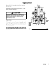
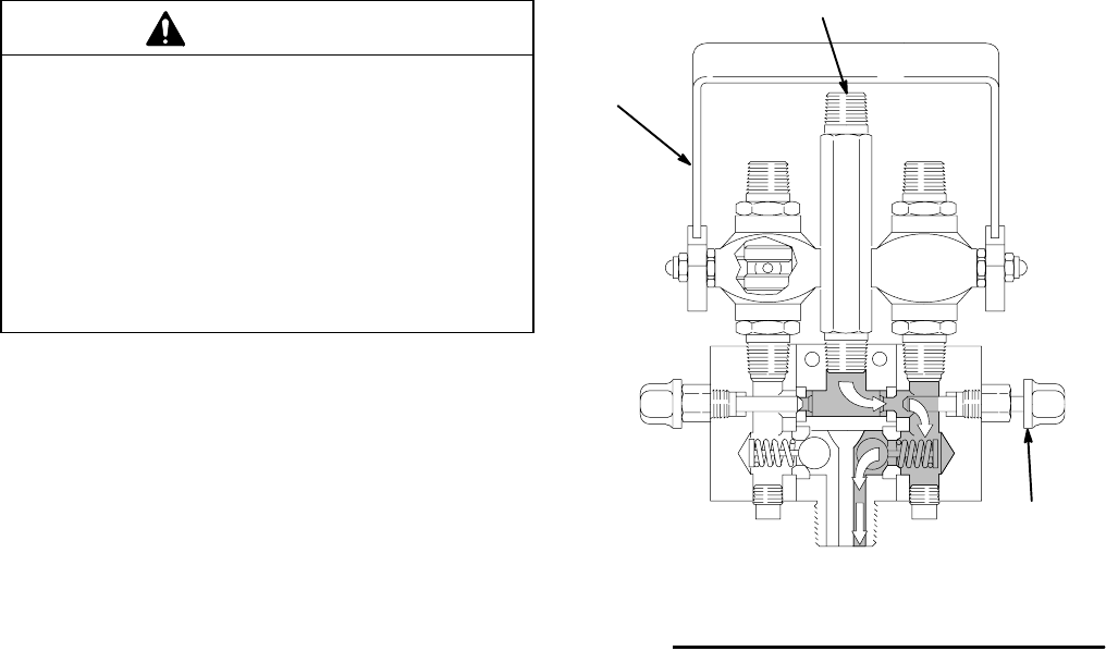
Fig 2 shows the handle in the UP, or closed, position and the
right solvent valve open with solvent flowing through the
right fluid chamber and out through the mixing chamber.
Handle
up
Fig. 2
05767
Solvent out
Solvent
Resin
(A)
Hardener
(B)
Solvent
valve
shown
open


