44
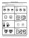
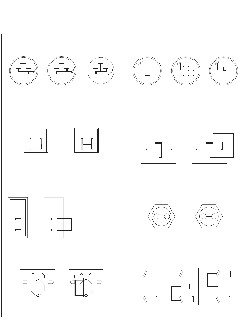
CONTINUITY DIAGRAM
Model 9870070, 071, 072
OFF
M
G
S2
B
S1
A
RUN
M
G
S2
B
S1
A
START
M
G
S2
B
S1
A
Key Switch (071, 072)
(03602300)
PTO & FWD/REV Switch
(02913100)
1
2
1
2
(BUTTON UP) (BUTTON DOWN)
Solenoid
(03492300)
NOT ENERGIZED ENERGIZED
OFF
ON
Light Switch
(08973300)
Seat Switch
(03654200)
1
2
OPERATOR
OFF SEAT
1
2
OPERATOR
ON SEAT
Lift Pump Switch
(03437900)
DOWNUPOFF
F
D
B
C
A
E
F
D
B
C
A
E
F
D
B
C
A
E
Relay
(03042800)
87
87A
86 85
30
NOT ENERGIZED
87
87A
86 85
30
ENERGIZED
The diagrams below show the various states of connection for electrical components.
The solid lines on switches show continuity.
NOTE: All switches are viewed from the rear.
Key Switch (070)
(08883300)
OFF
M
G
S
B
L
A
RUN START
M
G
S
B
L
A
M
G
S
B
L
A
PJ0441


