


-14- Model H6082, H6083, and H6086 Heirloom Electric Guitar Kits
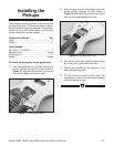
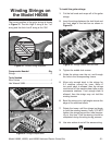
White
Red
Bare Wire
(Ground)
To Bridge
Pickup
To Volume
Control
To Neck
Pickup
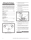
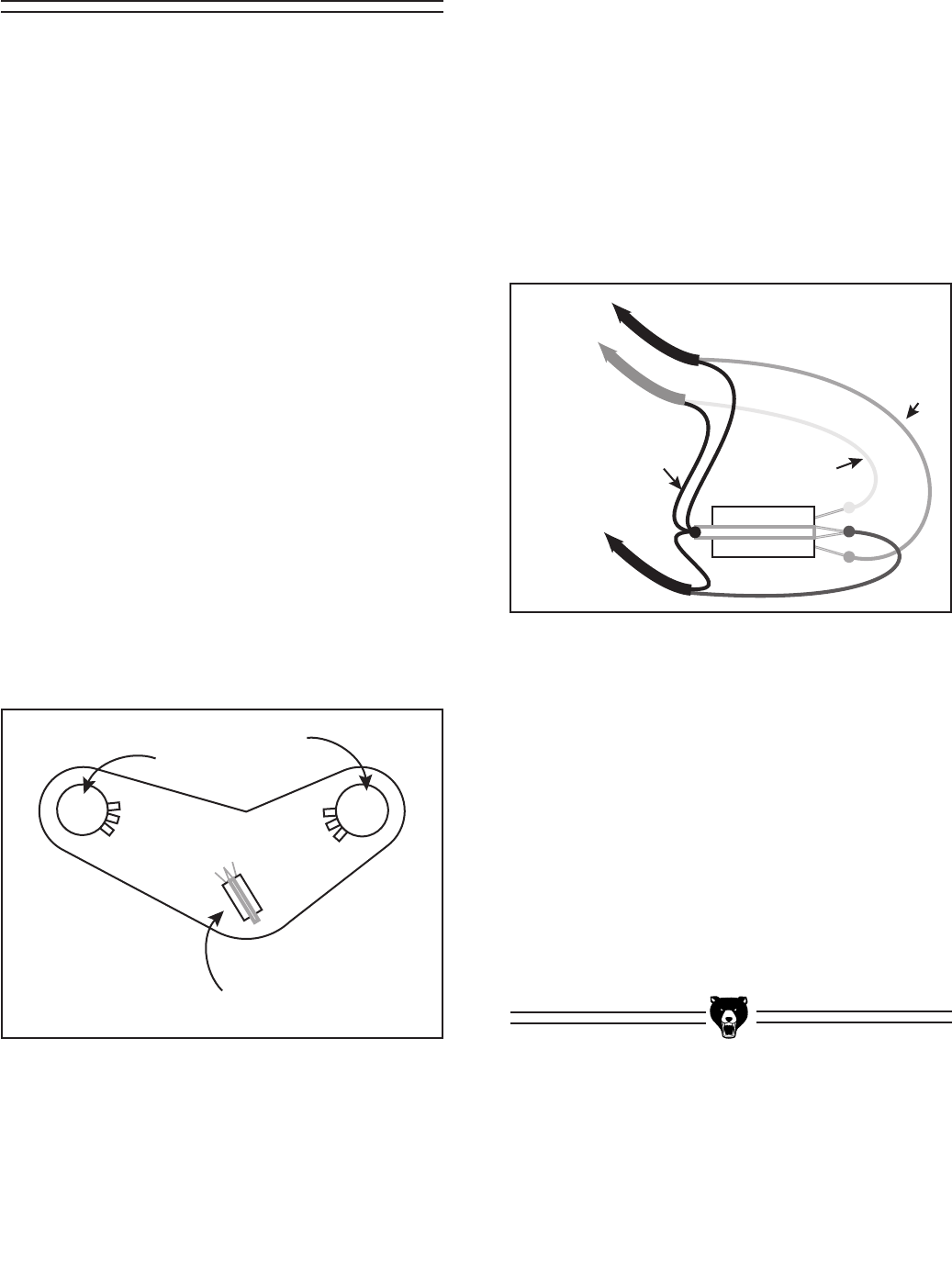
Figure 20. 3-way switch wiring.
6. Rotate the selector switch so the red wire
that leads to the neck pickup is towards the
front of the guitar.
7. Flip the guitar over and secure the selector
switch with the 12MM nuts and washers.
8. Feed the black ground wire through to the
tremolo cavity on the H6086, or to the bridge
insert hole for the Model H6082 and H6083.
9. Install the back cover plate over the electron-
ics cavity.
This guitar comes with a wiring harness that has
most of the components soldered in place. You
only need to solder in the pickup wires onto the
three way switch. Soldering the wires may cause
damage to the components if done incorrectly. If
you are unsure of your skills; do your research,
practice on scrap wires, or take it to a profes-
sional.
Components Needed Qty
Guitar ................................................................. 1
Wiring Harness ..................................................
1
Washer 8MM .....................................................
4
Nut 8MM ............................................................
4
Washer 12MM Gold ..........................................
1
Nut 12MM Gold .................................................
1
Back Cover Plate ...............................................
1
Tools Needed
Socket 11MM, 14MM ..........................................
1
Soldering Iron .....................................................
1
Solder ........................................................
Varies
To wire the pickups:
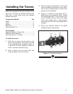
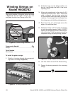
1. Place the pots and the selector switch in the
electronics cavity as shown in
Figure 19.
A500K
B500K
Selector Switch
Volume
Tone
Figure 19. Wiring diagram 1.
Wiring the Pickups
2. Flip the guitar over and secure the pots with
the 8MM nuts and washers.
3. Rotate the control pot shafts counterclock-
wise until they stop. Place the control knobs
over the control pot s
hafts with the 0 at the
12 o'clock position.
4. Push the audio jack out through the hole in
the end of the body.
5. Solder the pickups onto the selector switch
as shown in
Figure 20.