


24 Soundcraft MFXi MPMi User Guide Issue 1210
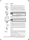
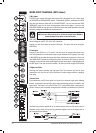
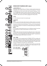
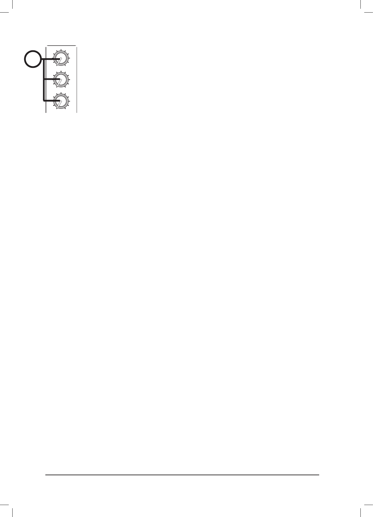
8 FX SEND (MFXi only)
This control sets the level of the post-fade signal being sent to the FX bus; from there it is routed
to the FX processor. The FX Send is xed post-fader.
9 PAN
This control sets the amount of the channel signal feeding the Left and Right MIX buses, allowing
you to move the source smoothly across the stereo image. When the control is turned fully left or
right you are able to route the signal at unity gain to either left or right outputs individually.
10 MUTE
All outputs from the channel (except inserts) are on when the MUTE switch is released and muted
when the switch is down, allowing levels to be pre-set before the signal is required. The MUTE switch’s
inbuilt LED glows when the channel is muted.
11 INPUT CHANNEL FADER
The 60mm FADER gives you smooth control of the overall signal level in the channel strip, allowing
precise balancing of the various source signals being mixed to the Master Section. It is important
that the input level is set correctly to give maximum travel on the fader which should normally be used
at around the “0” mark. See the “Initial Setup” section on page 42 for help in setting the right level.
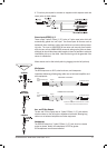
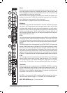
12 PFL
When the latching PFL switch is pressed, the pre-fade pre-mute signal is fed to the headphones,
control room output and meters, where it replaces the MIX. The SOLO LED on the Master section
illuminates to warn that a PFL is active. This is a useful way of listening to any required input sig-
nal without interrupting the main mix, for making adjustments or tracing problems. When PFL is
pressed anywhere on the console, the Control Room outputs automatically switch from monitoring
the Mix Outputs.
13 PEAK LED
This LED will light when the signal level approaches clipping at any of the three monitored points:
PRE-EQ, POST-EQ and POST-FADE.
14 SIGNAL PRESENT (SP) LED
The SP LED glows when a signal is present. The feed point for the LED is pre-EQ.
15 MIX/SUB
When this switch is up, the channel’s post-pan-pot signal is routed to the Mix (left and right) buses.
When the switch is depressed, the post-pan-pot signal is routed to the Sub-group (left and right)
buses.
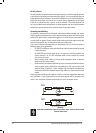
It is sometimes useful to route several inputs to the sub-group buses, e.g. all the mics for a drum
kit, or all the vocal mics for a choir. These signals can then be fed to the main mix at the master
section. By doing this the levels of all of the grouped inputs can be changed together by using the
group faders instead of having to adjust all of the individual input faders, although, of course, the
individual channel faders will have to be adjusted to start with.
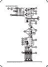
MIC
HF
LF
MF
1
33
6
6
99
12
12
15 15
0
-
+
33
6
6
99
12
12
15 15
0
-
+
33
6
6
99
12
12
15 15
0
-
+
750
150
3.5k
GAIN
PFL
MIX
SUB
PK
SP
5
0
-5
-10
-20
-30
MUTE
1
10
01
0
01
0
01
0
01
0
01
0
01
0
LR
AUX1AUX1
AUX2
AUX3
PAN
0
1
LINE
INSERT
1
2
4
5
6
10
11
7
12
3
8
14
13
9