


decreases by 10 dB. For every
+lV,
increases by 10 dB. So the
dynamic range of positive to negative power levels is dependent on
the synthesizer power level setting.
The input impedance for this input connector is factory set at
500,
but can be switched to 2
kfl.
Refer to “Adjustments” in
the Calibration manual. See “Specifications” for the electrical
requirements of the AM input. Damage levels for this input are
>+15V
or
<-15V.
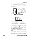
AUX OUTPUT provides a reference signal from 2 to 26.5 GHz at a
typical minimum power level of -10
dBm.
Nominal input impedance
is 50
0.
EXT ALC allows the synthesizer to be externally leveled. This input
is used for power meter leveling or negative crystal detector leveling.
Input impedance in crystal or meter leveling modes is nominally 1
MR. See “Specifications” for the signal requirements. Nominal input
impedance is 100
kR.
FM INPUT accepts a-8 to
+8V
signal when on the 1 MHz/V
sensitivity, or a -1 to
+lV
signal when on the 10 MHz/V sensitivity.
Any signal greater than these limits will cause distortion. The
deviation changes linearly as the FM input changes from 0 to its
upper or lower voltage limit. The input impedance for this input
connector is factory set at
500,
but can be switched to 60052. Refer
to “Adjustments” in the Calibration manual. Damage level for this
input is
>15V
or
<-15V.
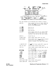
PULSE INPUT is TTL compatible. A TTL high input
(>+2V)
causes a maximum selected RF power output, while a TTL low input
causes minimum RF output
(>80
dB RF on/off ratio). Nominal
input impedance is 50 R. When using internal pulse generator, a
TTL-level pulse sync signal preceding the RF pulse by nominally
70 ns is produced at this connector. The electrical requirements of
the PULSE INPUT are detailed in “Specifications”. The damage
levels for this input are
>+5.5V
or
I-0.5V.
PULSE SYNC OUT (Option 002 only) Outputs a 50 ns wide TTL
pulse synchronized to the leading edge of the internally-generated
pulse.
PULSE VIDEO OUT (Option 002 only). Outputs the pulse
modulation waveform that is supplied to the modulator. This can be
either the internally- or externally-generated pulse modulation.
SWEEP OUTPUT provides a voltage range of 0 to i-10 V. When
the synthesizer is sweeping, the SWEEP OUTPUT is OV at the
beginning of the sweep and
+lOV
at the end of the sweep regardless
of the sweep width. In CW mode, the SWEEP OUTPUT ranges
from 0 V at the synthesizer minimum frequency to
+lO
V at the
specified maximum frequency, with a proportional voltage for
frequencies between the specified minimum and maximum. When the
synthesizer is in manual sweep operation the sweep output voltage is
a percentage of the span. Minimum load impedance is 3
kR.
HP 8360
User’s Handbook
Operating and Programming Reference
C-5