


Introduction
Thank you for purchasing the Korg TP-2 Dual Tube Preamp w/
Optical Compression and Digital Output. In order to enjoy long
and trouble-free use, please read this owner’s manual carefully,
and use your TP-2 only as directed.
Features
The TP-2 is a dual-channel preamp featuring two 12AX7 vacuum
tubes, plus fast operating and transparent optical compression
and limiting circuitry. Designed to accept a variety of sources
over a wide range of levels, it is ideal for your most critical and
demanding recording applications.
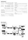
In addition to both XLR and 1/4” TRS balanced outputs, the TP-
2 also features both optical and coaxial digital outputs (S/P DIF
format) allowing it to interface with other digital equipment, or
to serve as a stand alone AD converter.
Using a specially tuned version of our acclaimed Valve Force
circuit, the TP-2 delivers the robust, musical warmth and mid-
low region presence typical of vacuum tubes. The optical
compression responds quickly and transparently, providing a
distinctly full analog body without adversely coloring the sound.
In addition, the optical compressor’s gain reduction and limiting
circuitry allow you to avoid any audio clipping while you’re
recording.
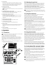
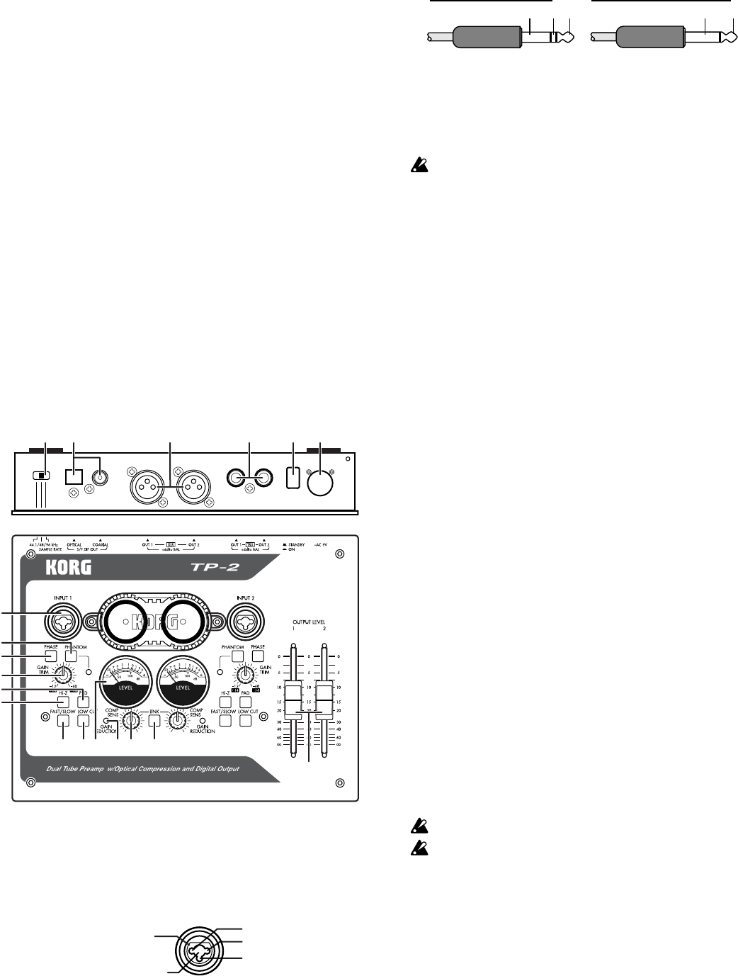
1. Parts and their function
7 89 11 1210
14
15
16 17 18
1
2
3
4
5
6
13
19
1. INPUT 1, INPUT 2 jacks
These are balanced inputs that combine XLR jacks and 1/4” TRS
phone jacks.
Unbalanced phone plugs may also be connected to the 1/4” jacks.
If you are using a condenser mic requiring phantom power, connect it
to the XLR jack.
1/4" TRS phone jack
XLR jack
2: HOT
1: GND
3: COLD
If you are using a guitar or the line output from an instrument,
connect it to the TRS phone jack.
GND
COLD
HOT
GND HOT
Balanced phone plug Unbalanced phone plug
2. Phantom power switch/LED
This switch supplies +48V phantom power to condenser mics. The
LED will light if +48V power is being supplied. Power is supplied
only to the XLR jack. Turn this off (LED dark) if you’re using a
dynamic mic.
If a condenser mic is connected or disconnected with the phantom power
switch on, damage to your equipment may occur. For this reason, always
turn the phantom power switch off before connecting or disconnecting a
condenser mic.
3. Phase switch
If you are inputting a stereo source from audio equipment in which
the hot and cold pins are wired in reverse, the stereo image may be
unsteady or cancellation may occur. By pressing this switch in,
you can invert the phase of the input signal by 180 degrees to
compensate.
4. Gain trim knob
This knob adjusts the input gain. If the PAD switch is on (pushed in),
the range is +14 – –34 dBu. If the PAD switch is off, the range is –12 –
–60 dBu.
5. Hi-Z switch
This switch changes the impedance level of the TRS phone jack to
high impedance. It is on when the switch is pushed in. Turn this
switch on when connecting a high output impedance device such as
guitar or bass.
6. PAD switch
This switch lowers the level of the input signal by 26 dB. The pad is
on when the switch is pushed in. When a line level input source is
connected, turning the pad on will allow the gain trim knob to have a
wider useful range of adjustment.
7. Compressor mode switch
This switch changes the compressor’s response speed. Use the Fast
setting for short sounds such as drums or percussion, and the Slow
setting (press the switch in) for more sustained sounds, such as
vocals.
8. Low cut switch
This switch activates a 70 Hz –6 dB/oct low cut filter.
Use this to reduce unwanted low-frequency content. The filter is on
when the switch is pressed in.
9. Level meter
The meter shows the audio level. If the needle moves into the red
area above 0 dB, this indicates that digital clipping is occurring.
Set the gain trim knob and the compressor sensitivity knob to prevent
the needle from exceeding 0 dB.
Place the unit horizontally so that the level meters operate correctly.
The level meters indicate the level of the signal before it is sent to the
output level faders.
10. Gain reduction LED
This LED will light when gain reduction is being applied by the
compressor.
11. Compressor sensitivity knob
This specifies the audio level where the compressor begins to kick in.
Turning the knob toward the right will increase the sensitivity, so that
compression will be applied even at low levels.
If you don’t want to apply compression, turn this knob all the way to
the left.