


11
Owner’s Manual
Owner’s Manual
loed channels, or the Tape input. The volume is adjust-
able with the CONTROL ROOM/SUBMIX [34]knob.
These balanced outputs are capable of delivering 22
dBu into a 600 ohm balanced or unbalanced load.
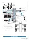
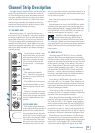
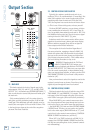
16. ALT 3–4 OUTPUT
These 1⁄4" outputs are the sum of any channels that
have the MUTE/ALT 3-4 [25] switch pressed in (see
page 13 for the tender details).
These balanced outputs are capable of delivering 22
dBu into a balanced or unbalanced load.
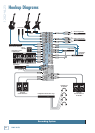
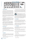
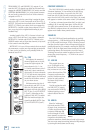
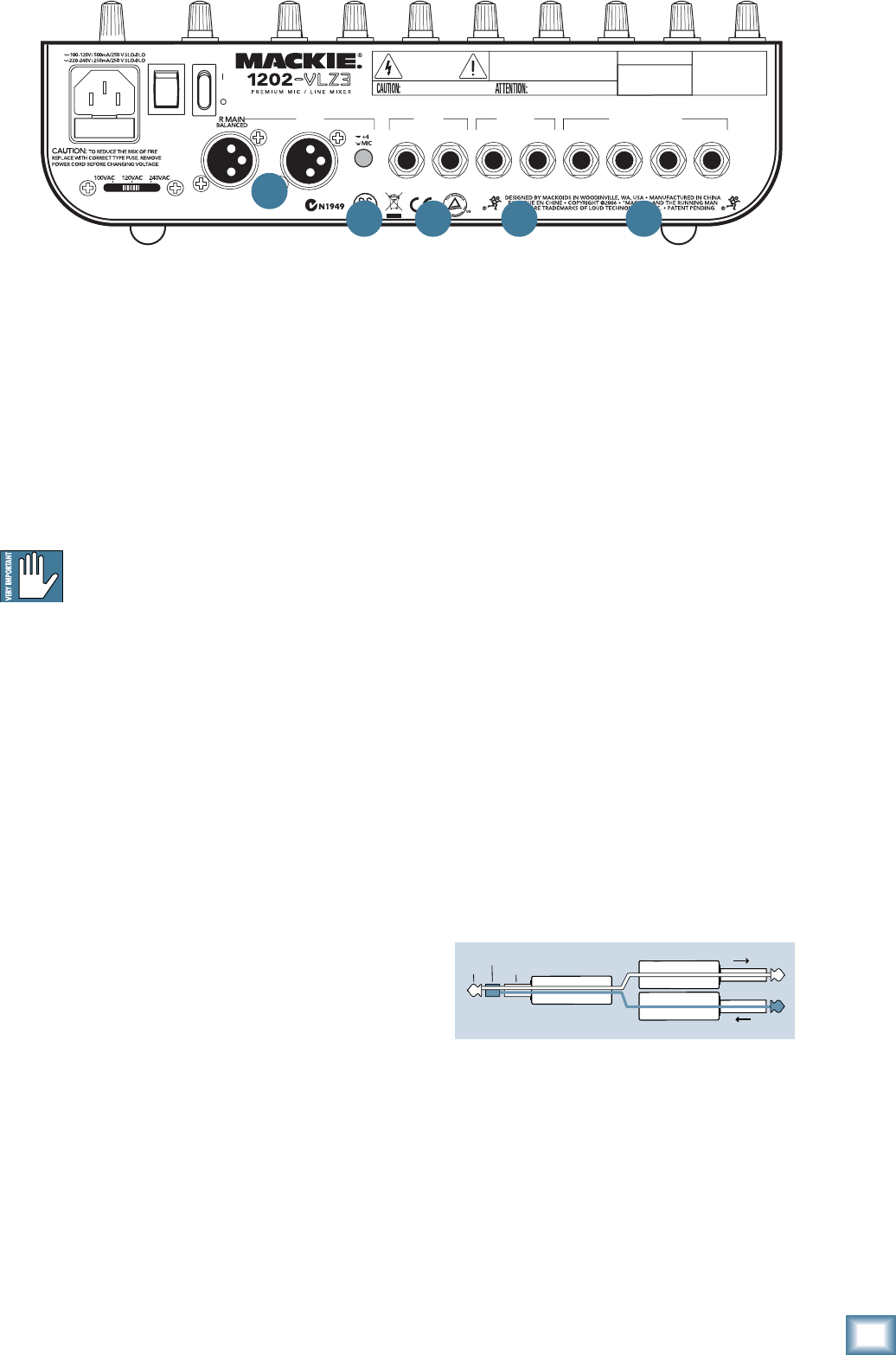
17. CHANNEL INSERT (Channels 1–4 )
These rear-panel jacks are where you connect serial
effects such as compressors, equalizers, de-essers, or
fi lters. Since most people don’t have more than a few of
these gadgets, we’ve included inserts for just the fi rst
four channels. If you want to use this kind of process-
ing on channels 5 through 12, simply patch through the
processor before you plug into the 1202-VLZ3.
The channel insert points are after the GAIN [4] and
LOW CUT [3] controls, but before the channel’s EQ
[27] and LEVEL [23] controls. The send (tip) is low-
impedance (120 ohms), capable of driving any line-level
device. The return (ring) is high-impedance (over 2.5 k
ohms) and can be driven by almost any device.
See Appendix B for details and drawings about Insert
cables, and a diagram showing three ways to use the
jacks.
Besides being used for inserting external devices,
these jacks can also be used as channel direct outputs;
post-GAIN, post-LOW CUT, and pre EQ. In fact, Mackie
mic preamps have become so famous, that people buy
these mixers just to have four of these in their arsenal.
12. PHONES
This stereo jack will drive any standard headphone
to very loud levels. Walkperson-type phones can also be
used with an appropriate adapter. To learn how signals
are routed to these outputs, see SOURCE MATRIX
[33] on page 16. If you’re wiring your own cable for the
PHONES output, follow standard conventions:
Tip = Left channel
Ring = Right channel
Sleeve = Common ground
WARNING: When we say the headphone
amp is loud, we’re not kidding. It can cause
permanent ear damage. Even intermediate
levels may be painfully loud with some earphones. BE
CAREFUL! Always turn the CTL ROOM/ SUBMIX [34]
knob all the way down before connecting headphones.
Keep it down until you’ve put the phones on. Then turn
it up slowly. Why? “Engineers who fry their ears fi nd
themselves with short careers.”
13. XLR MAIN OUTS
Use these to send the main mix out into the line-level
balanced inputs of your amplifi er or powered speakers.
These low-impedance outputs are fully balanced
and capable of driving +4 dBu lines with up to 28 dB
of headroom. This output is 6 dB hotter than other
outputs.
14. XLR MAIN OUTPUT LEVEL SWITCH
Engaging this switch reduces the level of the bal-
anced XLR main outputs by 40 dB, so you can feed the
microphone input of, say, another mixer. (You can safely
connect the XLR outputs into an input that provides 48V
phantom power.)
15. CONTROL ROOM
These 1⁄4" outputs are provided so you can listen
to something other than the main mix. The source is
selected using the SOURCE MATRIX [33] switches (see
page 16). You can choose to listen to the main mix, the
Alt 3-4 stereo bus (see MUTE/ALT 3-4 on page 13), So-
POWER
ON
PHANTOM
ON
L MAIN
MAIN
OUTPUT
LEVEL
4 3
R/4 L/3
CHANNEL INSERT
BAL/UNBALBALANCED BAL/UNBAL
ALT
OUTPUT
R
L
CONTROL
ROOM
SERIAL NUMBER
MANUFACTURING DATE
RISK OF ELECTRIC SHOCK
DO NOT OPEN
REPLACE WITH THE SAME TYPE FUSE AND RATING.
DISCONNECT SUPPLY CORD BEFORE CHANGING FUSE
UTILISE UN FUSIBLE DE RECHANGE DE MÊME TYPE.
DEBRANCHER AVANT DE REMPLACER LE FUSIBLE
WARNING:
TO REDUCE THE RISK OF FIRE OR ELECTRIC SHOCK, DO NOT
EXPOSE THIS EQUIPMENT TO RAIN OR MOISTURE. DO NOT REMOVE COVER.
NO USER SERVICEABLE PARTS INSIDE. REFER SERVICING TO QUALIFIED PERSONNEL.
CAUTION
CAUTION
AVIS:
RISQUE DE CHOC ELECTRIQUE — NE PAS OUVRIR
2 1
(
PRE-FADER / PRE EQ TIP SEND / RING RETURN
)
XDR
TM
EXTENDED DYNAMIC RANGE MIC PREAMPLIFIERS ARE PROPRIETARY TO MACKIE DESIGNS, INC.
ASSIGN
TO MAIN MIX
“tip”
This plug connects to one of the
mixer’s Channel Insert jacks.
“ring”
tip
ring
sleeve
SEND to processor
RETURN from processor
(TRS plug)
13
14 15 16 17