10
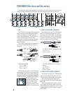
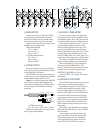
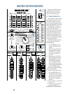
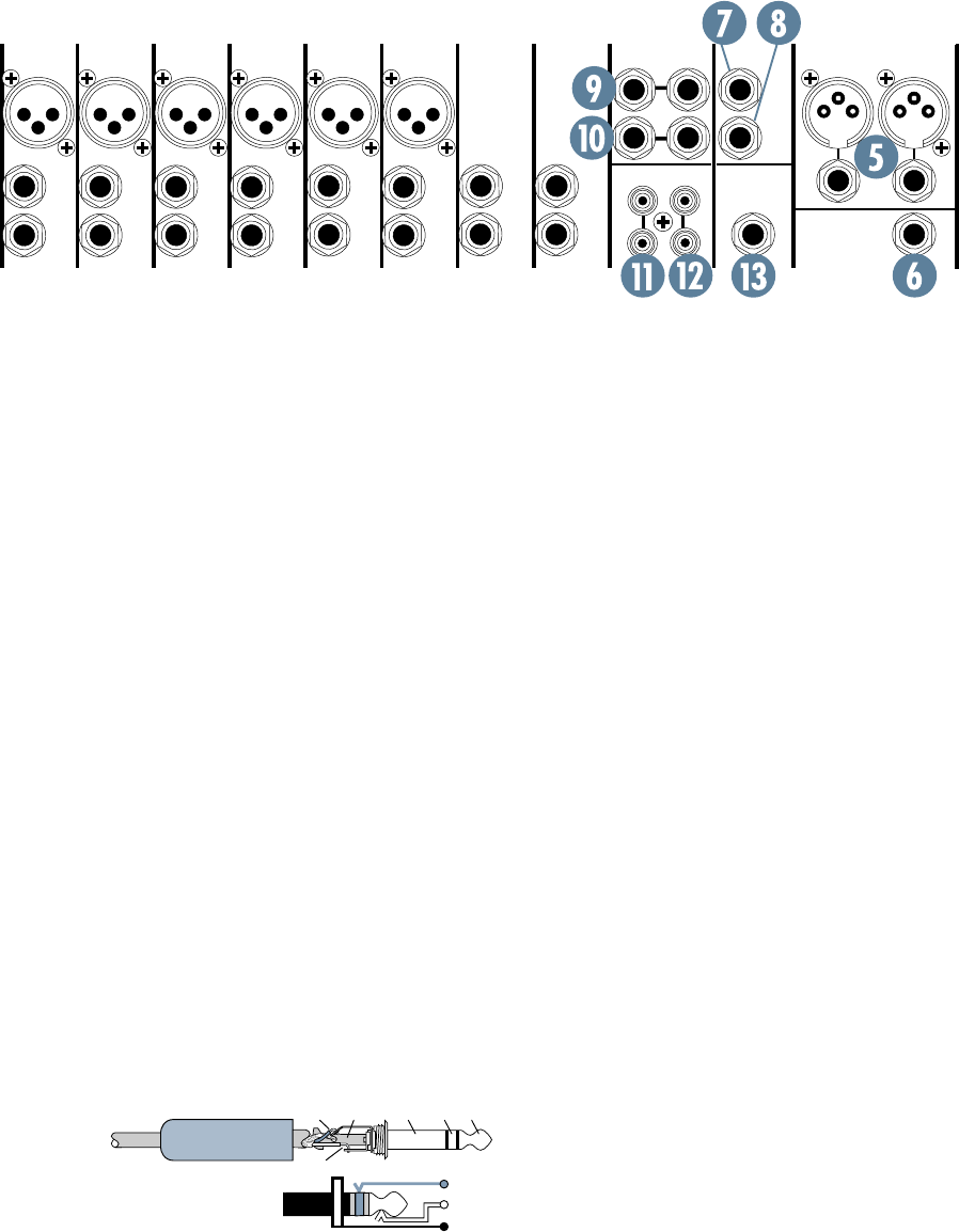
7. AUX SEND 1/MON OUTPUT
To create a stage monitor mix, patch this
TRS output into your monitor amplifier’s input,
or powered monitor’s input. This jack can also
be used to feed the inputs of an effects device.
Each channel strip has an AUX 1 (21) con-
trol knob which adjusts how much of that
channel’s signal appears at this output. The
output from this jack is the sum of all those
active channels which have their AUX 1 knobs
set more than in the minimum position. Use
the AUX 1/MON SEND (41) knob (page 17) to
control the overall output sent to your monitor.
The output is not affected by the main mix
faders, or channel faders, or by channel EQ.
The five band EQ (27) can be applied to
this output using the MAIN/AUX 1 (28)
switch. A sample of the stereo effects can also
be added to your monitor by adjusting the
EFFECTS TO MONITOR (42) knob.
See AUX 1/MON (21) on page 13 for more
information.
8. AUX SEND 2/EFX OUTPUT
This 1/4" TRS output can be used to connect
to the input of an external effects device.
Each channel strip has an AUX 2 (22) con-
trol knob which adjusts how much of that
channel’s signal appears at this output. The
output from this jack is the mix of all those ac-
tive channels which have their AUX 2 knobs
set more than minimum. Use the AUX 2/EFX
SEND (38) knob to control the overall output
sent to your external effects processor. The
EMAC internal effects processor receives the
same signal.
This output is not affected by the main mix
faders, the five-band EQ (27), or by the EMAC
internal effects.
As the output is post-channel-fader, and
post-channel EQ, it cannot be used as tradi-
tional stage monitor cues. It is intended to
patch into effects device inputs; hence the
name “EFX.” See AUX 2/EFX on page 13.
5. MAIN OUTPUTS
Coming in two flavors, XLR and 1/4" TRS,
the main output represents the end of the
mixer chain, where your fully mixed and en-
hanced stereo signal enters the real world.
Connect these outputs to the inputs of your
amplifier, or powered speakers.
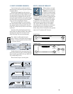
XLR balanced wiring:
Pin 1 = shield
Pin 2 = hot (+),
Pin 3 = cold (–)
1/4" TRS balanced wiring:
Tip = hot (+)
Ring = cold (–)
Sleeve = shield
6. PHONES OUTPUT
The stereo signal at this output jack is the
main mix, but it is not affected by the position
of the MAIN MIX (34) faders.
The PHONES (33) control knob allows you
to set the levels in your headphones as desired,
without disturbing the main mix level.
Note: Be very careful because the PHONES
jack can drive any standard headphones to
very loud levels. Please see the “Safety Instruc-
tions” on page 2 for information on hearing
protection.
1/4" TRS stereo wiring:
Tip = left, ring = right, sleeve = shield
Walkperson-type phones can also be used
with an appropriate adapter.
SLEEVE
TIPSLEEVE
TIP
RING
RING
TIP
SLEEVERING
9/10
11/12
MAIN OUT
1
1
MON
L
R
AUX SEND
STEREO AUX
RETURN
LEFT
7/8
5/6
MIC
MIC
4
MIC
3
MIC
2
1
MIC
MIC
BAL/UNBAL
L
LINE IN
BAL/UNBAL
L
RR
BAL/UNBAL
LINE IN
L
LINE IN
L
RR
LINE IN
BAL/UNBAL
BAL/UNBAL
LINE IN
INSERT
BAL/UNBAL
LINE IN
INSERT
BAL/UNBAL
LINE IN
INSERT
BAL/UNBAL
LINE IN
INSERT
(MONO) (MONO)(MONO) (MONO)
2
CD/TAPE
IN
TAPE
OUT
LL
RR
(MONO)
EFX
FOOT
SWITCH
PHONES
2
EFX
RIGHT
BAL/UNBAL


