


9
Owner’s Manual
Owner’s Manual
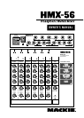
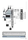
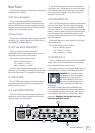
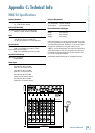
Rear Panel
The rear panel is where you make all your analog audio
connections to the HMX-56.
8. IEC Power Receptacle
This is a standard 3-prong IEC power connector.
Connect the detachable linecord (included in the box
with your HMX-56) to the power receptacle, and plug
the other end of the linecord into an AC outlet properly
configured for your particular model.
9. Power Switch
This one is self-explanatory. When the power switch is
turned ON (up), power is supplied to the HMX-56 and
the POWER [6] indicator lights up.
10. LEFT and RIGHT MAIN INPUT
These 1/4" TRS jacks accept a balanced or
unbalanced line-level input signal. Connect the main
mix output from the mixer to these inputs.
The
1/4"
TRS inputs are wired as follows:
Sleeve = Shield or ground
Tip = Positive (+ or hot)
Ring = Negative (– or cold)
If you are connecting a mono input signal to these
inputs, use a Y-Cord splitter to connect the signal to both
inputs. See “Mults and Y’s” in Appendix B for more info.
11. EFFECTS SEND
This 1/4" TRS output connector provides a balanced
or unbalanced line-level signal for connecting to the
input of an effects device.
12. L and R EFFECTS RETURN
These 1/4" TRS input connectors accept balanced or
unbalanced line-level stereo signals from an external
effects processor (or other device).
If you are connecting a mono effects return signal to
these inputs, use a Y-Cord splitter to connect the signal
to both inputs (otherwise you will only hear the effects
in one side of the headphones). See “Mults and Y’s” in
Appendix B for more info.
13. SOURCE INPUT A-D
These 1/4" TRS jacks accept a balanced or unbalanced
line-level input signal. This is the signal that you add
into the headphone mix when you adjust the SOURCE
A-D Level Controls [1] on each channel strip. You might
connect a submix output from the mixer to these inputs,
or a direct output from an individual channel (so the
talent can really crank themselves up in the headphone
mix if they want to).
These mono inputs are routed equally to the left and
right phones output.
The
1/4"
TRS inputs are wired as follows:
Sleeve = Shield or ground
Tip = Positive (+ or hot)
Ring = Negative (– or cold)
14. PHONES Out 1-6
Plug your headphones into these jacks. Each PHONES
output carries its own individual mix as determined by
the corresponding channel strip controls.
You can also connect an in-ear monitor (IEM) system to
the PHONES jack to provide an individual monitor mix.
WARNING: The headphone amps
are designed to drive any standard
headphones to a very loud level.
We’re not kidding! They can cause
permanent hearing damage. Even
intermediate levels may be painfully loud with some
headphones.
BE CAREFUL! Always start with the PHONES level
turned all the way down before connecting headphones
to the PHONES jack. Keep it down until you’ve put on
the headphones. Then turn it up slowly. Why? Always
remember: “Engineers who fry their ears, find
themselves with short careers.”
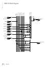
HMX-56
6 5 4 3 2 1
ABCDRLSENDR
L
RETURN
ON
MAIN INPUT
EFFECTS SOURCE INPUT
PHONES
90-120VAC
50/60 HZ 12W
.25A/250V FUSE