


and shall appear on the rear
panel as
1
⁄4" phone TRS
phone jacks. The jacks shall
be fitted with internal
switches to accommodate
monaural configuration, by
using only the left jack(s).
13. AUXILIARY RETURN
CONTROLS AND SWITCHES.
The mixer shall include 4
dual-channel auxiliary return
gain controls, each feeding
the main stereo buses. Auxil-
iary return #3 shall have its
signal source switchable be-
tween the auxiliary return #3
inputs or the signals avail-
able on the alternate (3–4)
mix outputs. Auxiliary return
#4 shall be assignable to
two different destinations,
feeding either the main left
and right buses or the
monitor system only.
14. MICROPHONE PRE-
AMPLIFIERS. The mixer
shall include two micro-
phone preamplifiers
mounted on the rear of the
mixer frame. Each micro-
phone preamplifier shall
feature electronically
balanced transformerless
inputs using female
XLR-3-type connectors with
gold-plated pins, a rotary
sensitivity control adjust-
able from –50 dBu to –10
dBu, and a line-level im-
pedance-balanced output
appearing at a
1
⁄4" TRS
phone jack. Globally switch-
able phantom power shall
be available at the
microphone inputs.
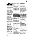
15. MIXER EXPANDER
FUNCTION. The mixer buses
shall accommodate up to
48 additional stereo input
channels when connected
to up to 3 Mackie Designs
LM-3204E Expander units.
The mixer shall be fitted with
a 20-pin IDC-type “expander
input” connector mounted
on the rear of the mixer
frame, which shall carry all
audio and control signals
2
2
accommodating a total of
2 stereo auxiliary send
buses and 2 monaural
auxiliary send buses.
7. MAIN OUTPUT CONNEC-
TIONS. The mixer shall have
electronically balanced, line-
level left and right main out-
puts, appearing as
1
⁄4" TRS
jacks (tip hot, ring cold) on
the rear panel. Additionally,
the main buses shall offer
left and right unbalanced
insert connections, appear-
ing on the rear panel as
1
⁄4"
phone TRS jacks.
8. OTHER OUTPUT AND
MONITORING CONNEC-
TIONS. The mixer shall have
the following balanced line-
level connections, appearing
as
1
⁄4" TRS jacks on the rear
panel: left and right alter-
nate (3–4) outputs, left and
right control room outputs.
For convenience, the left
and right main outputs and
the left and right tape moni-
tor inputs shall also appear
as RCA phono jacks on the
rear panel. There shall also
be a stereo headphone out-
put on the front panel of the
mixer, carrying the control
room monitor signals at lev-
els and impedances proper
for headphones. The head-
phone output connection
shall be a stereo
1
⁄4" TRS
jack (tip left, ring right).
9. OUTPUT AND MONI-
TORING CONTROLS AND
SWITCHES. The mixer shall
include 2 linear fader con-
trols for gain adjustment of
the main L/R outputs, cov-
ering a range from infinite
attenuation to +10 dB
above unity gain. A tape
monitor switch shall alter-
nately select either the
main L/R outputs or the
signal at the tape inputs as
the source for the control
room and headphones
monitoring circuits. There
shall be a stereo linear
fader control for level ad-
justment of the control
room monitor output, and
a stereo rotary control for
level adjustment of the
headphone monitor output.
The mixer shall have a
stereo control for adjust-
ment of the monitoring
level of the internal solo
signals, and a blinking LED
to indicate channel solo
condition. Additionally, any
soloed channel(s) shall
have their -20 and O/L
LEDs light steadily, to indi-
cate a solo condition.
10. OUTPUT METERING.
The mixer frame shall in-
clude 2 12-segment LED
meters each displaying a
signal range from –40 dBu
to +10 dBu, each with an
additional LED indicating
mixer clipping level at +22
dBu. The meters shall moni-
tor the main left and right
output channels; alternately,
the meters shall monitor the
tape return signals when
the tape monitor switch is
depressed; or, the soloed
input channel signals when
any combination of solo
switches is depressed.
11. AUXILIARY SEND CON-
NECTIONS. The mixer shall
include balanced line-level
outputs from the auxiliary
send buses. The left and
right outputs of the 2 stereo
auxiliary send buses and the
outputs of the 2 monaural
send buses shall appear on
the rear panel as
1
⁄4" TRS
phone jacks (tip hot).
12. AUXILIARY RETURN
CONNECTIONS. The mixer
shall include 4 stereo auxil-
iary return inputs. Each aux-
iliary return shall have a left
and a right unbalanced line-
level input, accommodating
a nominal line level of be-
tween –10 dBV and +4 dBu,