


6
MR5mk2
MR5mk2
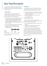
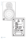
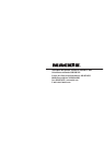
Rear Panel Description
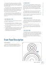
2. INPUT LEVEL
The MR5mk2 expects a line-level signal at its input.
Use this control to adjust the sensitivity of the input
section according to the signal strength at its input.
• The MR5mk2 is designed to operate with a +4 dBu sig-
nal when the input level control is in the max position.
In other words, wide open.
• Refer to the Quick Start section on page 5 for the
level-setting procedure.
3. HIGH FREQUENCY FILTER
This switch tailors the overall high-frequency
response by ±2 dB at 5 kHz and above. Leave this switch
in the “0 (NORMAL)” position unless:
• You want to subtly brighten or darken the sound of the
speakers.
• Perhaps you have hearing loss caused by too many
nights in front of a double Marshall stack.
• You just like to mix on the bright side or dull side.
If the mixes consistently sound dull or dark when
you listen elsewhere, this usually indicates that the
monitors are too bright, relative to your normal hearing.
A bit less high-frequency energy usually fixes this, and
the mix may be forced in this direction by reducing the
high-frequency output of the monitors by using the –2 dB
position of the switch.
This is where the signal is connected to the monitor
and adjustments are made to the frequency response
of the speakers to match the monitor’s location and the
room’s environment.
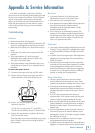
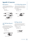
1. SIGNAL INPUTS
There are three types of input connectors: XLR,
1/4-inch, and RCA. Since all three of them are
connected together electrically, do not connect more
than one signal at a time to the input jacks.
• The XLR connector and 1/4-inch TRS (tip-ring-sleeve)
connector accept a balanced signal while the RCA
connector accepts an unbalanced signal. A balanced
signal provides better noise rejection and is the
preferred method, especially if using a cable longer than
20 feet (6 meters).
• The 1/4-inch TRS jack may also accept an unbalanced
signal from a 1/4-inch TS (tip-sleeve) plug.
The connectors are wired as follows (per the
AES/IEC standard):
XLR TRS RCA
Hot (+) Pin 2 Tip Tip
Cold (–) Pin 3 Ring —
Shield (Ground) Pin 1 Shield Shield
For more information on these connectors, see
Appendix B on page 11.
LOW FREQ
FILTER
HIGH FREQ
FILTER
0
–
2dB
+
2dB
+
2dB
+
4dB
CAUTION: REPLACE WITH THE SAME FUSE AND RATING.
DISCONNECT SUPPLY CORD BEFORE CHANGING FUSE.
(NORMAL)
0
(NORMAL)
LEVEL
INPUT
OFF MAX
THIS DEVICE COMPLIES WITH PART 15 OF THE FCC RULES FOR
THE U.S. AND ICES-003, FOR CANADA. OPERATION IS SUBJECT
TO THE FOLLOWING TWO CONDITIONS: (1) THIS DEVICE MAY
NOT CAUSE HARMFUL INTERFERENCE, AND (2) THIS DEVICE
MUST ACCEPT ANY INTERFERENCE RECEIVED, INCLUDING
INTERFERENCE THAT MAY CAUSE UNDESIRED OPERATION.
WARNING:
TO REDUCE THE RISK OF FIRE OR ELECTRIC
SHOCK, DO NOT EXPOSE THIS EQUIPMENT TO RAIN OR
MOISTURE. DO NOT REMOVE COVER. NO USER SERVICEABLE
PARTS INSIDE. REFER SERVICING TO QUALIFIED PERSONNEL.
AVIS:
RISQUE DE CHOC ELECTRIQUE — NE PAS OUVRIR
SERIAL NUMBER
REVISION
ON
(BALANCED)
(BALANCED)
(UNBALANCED)
XLR
RCA
TRS
ON
INPUT
SETTINGS
1 2
3
4
6
7
5