


Your connecting cables have not yet been fitted with plugs
In this case ensure that the plugs are correctly fitted to the coax cable. Use high frequency
screened plugs to avoid external radiation and interference. Only use broadband amplifiers
and splitters with a range from 5 - 1000 MHz.
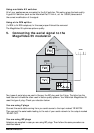
Attention: If you want to use the infrared return channel for your remote
control (see chapter 6) then the aerial wall outlets, amplifiers and splitters
that are included IN the cabling between your bedroom and living room
should be “return channel” compatible (5 – 30 MHz).
6. Setting the channel
The audio/video signal that has been added (e.g. from a DVD player) is converted into a normal TV
channel.
Using the MegaVideo 55 you can, in principle, choose any free channel. It is important to select a
free channel that is not already being used for an existing TV channel. The channels that are free
depend on the incoming aerial signal. For details consult the channel table supplied by your cable
company or, if you have your own aerial, the channel summary in your TV magazine.
1. Connect one of the two power adapters to the modulator and plug it into the mains.
2. Check your channel table and find two free channels that are adjacent. Now select the
higher of these two channels. Example: if channels 37 and 38 are free then select channel
38. If three adjacent channels are free select the middle channel.
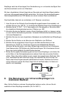
3. Set your selected channel using the dip switches on the front of the modulator.
The white dip switches can be set in two positions: ON (= 1, switch up) and OFF (= 0, switch
down). The combination of switches determines the channel setting. It is easier to do this
using a small screwdriver or a ballpoint pen.
You can find the correct dip switch positions for the channel you have selected in the table at
the end of this manual. For instance, channel 38 would be 01100100. The 2nd, 3rd and 6th
dip switches are ON (up) and the remaining dip switches are OFF (down).
Attention:
• The leftmost 7 switches (1 to 7 incl.) are for setting the channel.
• The 8th switch is used to turn the test picture on or off (up is on). That is
why this switch is normally shown in the 0 position in the attached list.
• If there is a 9th switch it has no function.
4. After you have set the channel you can turn on a test pattern using the 8th dip switch.
To do this set the dip switch to ON (= 1). This pattern consists of a number of black and
white bars on the screen.
6 MARMITEK