


1. LOUDSPEAKER OUTPUTS
WARNING! Never use the amplifier without a load attached!
There are two parallel loudspeaker output jacks provided for connection to
speaker extension cabinet(s). Please always ensure that the amplifier's output
impedance selector is set correctly (see item 2) and ALWAYS ensure you use
good quality speaker (unshielded) cables. NEVER use guitar (shielded) cables.
Always use a non-screened Marshall approved speaker lead when connecting an
extension cabinet.
2. OUTPUT IMPEDANCE SELECTOR
Matches the amplifier’s output to the load (speaker) impedance.
Your 1959RR should be completely powered down before the Output Impedance
Selector is turned.
As is the case with any Marshall all-valve amplifier it is imperative that: a) the
amplifier is connected to a load whilst in operation and b) the impedance selected
on the amplifier matches the total impedance of the extension speaker cabinet(s)
being used.
1x16 Ohm cabinet - Selector on 16 Ohm - Use either speaker output
2x16 Ohm cabinets - Selector on 8 Ohm - Use both outputs
1x8 Ohm cabinet - Selector on 8 Ohm - Use either output
2x8 Ohm cabinets - Selector on 4 Ohm - Use both outputs
1x4 Ohm cabinet - Selector on 4 Ohm - Use either output
WARNING! Do NOT use any other combination of cabinets and/or
impedances. Doing so may result in damage to the amplifier! An extension
speaker cabinet with an impedance of less than 4 Ohms, or two extension
cabinets of 4 Ohms or less should NOT be used with this amplifier.
Failure to comply with any of the points raised in this section will result in damage
to the amplifier.
3. MAINS SELECTOR
Matches the amplifier’s mains transformer to the
incoming mains voltage.
Your 1959RR should always be completely
powered down before the mains selector is
turned.
WARNING! ALWAYS ensure that this rotary selector is set to the correct mains
voltage applicable for the country where the 1959RR is being used. If you do not
know, consult your authorised Marshall dealer. Adjusting the selector from
230V/220V to 120V/110V/100V or vice-versa will require the mains fuse
(item 5) to be changed to the correct value as detailed on the rear panel.
4. MAINS INPUT
Your amp is provided with a detachable mains (power) lead, which is connected
here. The specific mains input voltage rating that your amplifier has been built for
is indicated on the back panel. Before connecting for the first time, please ensure
that your amplifier is compatible with your electricity supply. If you have any
doubt, please get advice from a qualified technician. Your Marshall dealer will
help you in this respect.
5. MAINS FUSE
The correct value of mains fuse is specified on the rear panel of the amplifier.
NEVER attempt to bypass the fuse or fit one of the incorrect value.
6. H.T. FUSE
The correct value of this H.T. fuse is specified on the rear panel of the amplifier.
NEVER attempt to bypass the fuse or fit one of the incorrect value.
Technical Specification
Power Output - 100W RMS
Weight - 21.4 kg
Size - 740mm x 270mm x 210mm
* EUROPE ONLY - Note:
This equipmenthasbeentestedand
foundtocomplywiththerequirementsoftheEMCDirective
(EnvironmentsE1,E2andE3EN55103-1/2)andtheLow Voltage
DirectiveintheE.U.
*EUROPEONLY -Note:
ThePeakInrush
currentforthe1959RRis 38amps.
1. POWER SWITCH
This is the On/Off switch for mains power to the amplifier. It will light up when
your amplifier is receiving the correct mains power and is switched on. It will not
be lit when the amplifier is switched off and/or is not receiving mains power.
Note: Please ensure the amplifier is switched off and unplugged from the mains
electricity supply whenever it is moved.
2. STANDBY SWITCH
The Standby Switch is used in conjunction with the Power Switch (item 1) to ‘warm
up’ the amplifier before use and to prolong the life of the output valves. When
powering up the amplifier always engage the Power Switch first, leaving the
Standby switch on ‘Standby’.This allows the application of the voltage required
to heat the valves to their correct operating temperature. After approximately two
minutes the valves will havereached the correct operating temperature and the
Standby Switch can be engaged. In order to prolong valve life, the Standby
Switch alone should also be used to turn the amplifier on and off during breaks in
a performance. Also, when switching off, always disengage the Standby Switch
prior to the main Power Switch.
Note: The following four controls - PRESENCE (4), BASS (5), MIDDLE (6) &
TREBLE (7) - are all shared, meaning that they all work on both Channel I and
Channel II. The Treble, Middle and Bass controls are highly interactive and
altering one control can change the way the other two behave. For this reason,
experimentation is recommended.
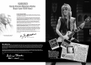
Randy’s preferred settings are shown on the panel above.
3. PRESENCE CONTROL
This control operates in the 1959RR’s power section and adds high frequencies to
your sound by altering the power amplifier’s negative feedback. Turning this
control clockwise adds more edge and ‘sparkle’ to your sound, making it crisper
and more cutting.
4. BASS CONTROL
This adjusts the bottom end, turning it clockwise increases the amount of low
frequencies in the sound.
5. MIDDLE CONTROL
This adjusts the level of those all-important mid-range frequencies. Turning it
clockwise increases the mids and fattens your sound, giving it more punch.
Turning it anticlockwise reduces the mids.
6. TREBLE CONTROL
This adjusts the top-end. Turning it clockwise increases the amount of high
frequencies (treble) present in the sound, making your tone brighter.
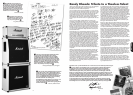
Tone/Tech talk - The modified Valve 1 stage
Unlike astandard Marshall 1959 Super Lead amplifier your Randy Rhoads
model contains amodification that increases gain and therefore extra distortion
within the circuit. This modification ‘hot rods’ the amplifier making it easier to push
it into the saturation levels necessary for the sound that Randy needed for his
musical station.
The change is very simple but effective and involves ‘cascading’ (feeding the
output of the first stage into the input of the second stage) the two halves of
valve 1. Traditionally, each half would serveas input buffer/first gain stage for the
two channels, i.e. one half for channel 1 and the other for channel 2, from there
they would separately feed the respective signals to the next stage which would
mix them, further amplify them and feed them to the tone stack.
Cascading valve 1 results in the guitar signal being increased by around 36dB or
60 times, much larger than it would normally be at this point in the circuit.
Subsequent stages then try to amplify this larger signal by similar amounts and
quickly run out of headroom causing the waveform to distort severely. The two
channel volumes still remain functional after the modification but adopt different
roles for their affect on the tone, allowing control of the extra gain and volume.
Plugging into channel 2routes the guitar signal through the whole cascade circuit
while plugging into channel 1 allows you to bypass the cascade and use the amp
in its standard format where ‘Volume 1’ will function as it normally would.
Standard Channel 2 format is sacrificed due to the modification.
7. VOLUME I
This controls the overall output level of Channel I, turning it clockwise increases the
volume. This channel is voiced for a higher treble response. In full cascade mode,
this controls the amount of signal amplified by the second half of valve 1, thereby
acting as a crude master volume for the whole cascade circuit and can also be
thought of as a further gain control for the boosted signal to the subsequent
stages of the preamp. In standard mode i.e. guitar plugged into channel 1, it
functions just likea normal unmodified 1959 Super Lead volume control.
8. VOLUME II
Full cascade mode. This controls the amount of signal amplified by the first half of
valve 1 that is fed to the second half, thereby acting as a gain control for the
cascade circuit itself.
9. HIGH SENSITIVITY INPUT FOR CHANNEL I
This is the ‘high sensitivity’ guitar input for Channel I - the brighter of the two
channels -and is the most commonly used input on standard unmodified models.
Always use a high quality screened guitar lead. NOTE - Plugging into this input
bypasses the cascade and the amp functions in standard format.
10. LOW SENSITIVITY INPUT FOR CHANNEL I
This is the ‘lowsensitivity’ guitar input for Channel I.Itis 6dBlower (half) than the
‘high sensitivity’ input and results inless gaincapability which may be required for
guitars withvery hot output pickups or active circuitry onboard.NOTE- Plugging
into thisinput also bypasses the cascade andthe amp functions instandard format.
11. HIGH SENSITIVITY INPUT FOR CHANNEL II
Plugging into this input enables the full cascade.
12. LOW SENSITIVITY INPUT FOR CHANNEL II
Plugging into this input enables the full cascade. It is 6dB lower (half) than the
‘high sensitivity’ input and results in less gain capability which may be required for
guitars with very hot output pickups or active circuitry onboard.
8
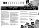
1959RR front panel features
Front panel
- Randy’s preferred settings shown
Rear panel
1959RR rear panel features
1
1 2 3 4 5 6
2 3 4 5 6 7 8 10 12
119
ENGLISH