


54
ENGLISH
ENGLISH
=c`^ eYV :YRZc^R_
@_ec`UfTeZ`_
KVTY_ZTR] @_W`c^ReZ`_
=c`_e GR_V] =VRefcVd
IVRc GR_V] =VRefcVd
1. MAINS (POWER) SWITCH
This is the On/Off switch for the mains electric power to the
amplifier.
Note: Please ensure the amplifier is switched off and unplugged
from the mains electricity supply whenever it is moved!
2. STANDBY SWITCH
The Standby Switch is used in conjunction with the Power Switch
(item 1) to ‘warm up’ the amplifier before use and to prolong the
life of the output valves. When powering up the amplifier always
engage the Power Switch (1) first, leaving the Standby switch on
‘Standby’. This enables the heater voltage, allowing the valves to
come up to their correct operating temperature. After
approximately two minutes the valves will have reached their
correct operating temperature and the Standby Switch can be
engaged, enabling the HT without ‘shocking’ cold valves. In order
to prolong valve life, the Standby Switch alone should also be
used to turn the amplifier on and off during breaks in a
performance. Also, when switching off, always disengage the
Standby Switch prior to the main Power Switch.
3. INDICATOR
This 6.3 Volt incandescent filament indicator will light up
whenever the Super 100JH is plugged into the mains and the
Mains Switch (1) is on.
4. PRESENCE CONTROL
This control affects high frequency content in the negative
feedback derived from the Super 100JH’s power section and fed
back to the phase inverter. Turning it clockwise adds an extra
high cut to your sound.
5. BASS CONTROL
This adjusts the bottom end. Turning it clockwise increases the
amount of low frequencies in the sound.
6. MIDDLE CONTROL
This adjusts the level of those all-important mid-range
frequencies. Turning it clockwise increases the mids and fattens
your sound, giving it more punch. Turning it anticlockwise reduces
the mids, producing a more 'scooped' tone.
7. TREBLE CONTROL
This adjusts the top-end. Turning it clockwise increases the
amount of high frequencies present in the sound, giving your
guitar tone a brighter edge.
Note: The previous four controls - PRESENCE (item 4), BASS
(item 5), MIDDLE (item 6) & TREBLE (item 7) - are all shared,
meaning that they are common to both of the amp’s channels -
Channel 1 and Channel 2. They are very interactive and,
consequently, altering one control can change the way the others
behave. For this reason, experimentation is recommended.
8. LOUDNESS 1
This controls the overall output level of Channel 1, turning it
clockwise increases the volume. This channel is voiced for a
higher treble response than the amp's other channel, Channel 2,
hence its ‘High Treble’ labelling.
9. LOUDNESS 2
This controls the overall output level of Channel 2, turning it
clockwise increases the volume level. This channel is voiced for a
flatter, more ‘normal’ response and is labelled ‘Normal’
accordingly.
10. TOP (HIGH SENSITIVITY) INPUT FOR CHANNEL 1
This is the ‘high sensitivity’ guitar input for Channel 1, the High
Treble channel. It is the most commonly used input.
Note: Always use a high quality screened guitar lead.
11. BOTTOM (LOW SENSITIVITY) INPUT FOR
CHANNEL 1*
This is the ‘low sensitivity’ guitar input for Channel 1. Its sensitivity
is configured to be 6dBr (decibels) lower than the channel’s ‘high
sensitivity’ input.
*Note: There is photographic and film evidence that Jimi used
this input rather than the high sensitivity input on certain
occasions. A particularly famous example of this can be seen in
the footage of his now legendary live performance of ‘Hey Joe’
and ‘Purple Haze’ at the Marquee Club, London, on March 2nd,
1967, for the TV show, Beat Club.
12. TOP (HIGH SENSITIVITY) INPUT FOR CHANNEL 2
This is the ‘high sensitivity’ guitar input for Channel 2, the Normal
channel.
13. BOTTOM (LOW SENSITIVITY) INPUT FOR
CHANNEL 2
This is the ‘low sensitivity’ guitar input for Channel 2. Once again
it is 6dBr lower than the channel’s ‘high sensitivity’ input.
Per
formance Note: ‘Jumping’ the two channels and
‘Daisy Chaining’ amps.
Because both channels of the Super 100JH have the same
number of gain stages and are in phase with each other, it is
possible to ‘jump’ (a.k.a. ‘link’ or ‘bridge’) them together and use
them both at the same time. Doing this enables you to expand
upon the amp's tonal capabilities.
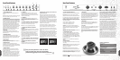
The most common way of doing this is to plug your guitar into the
top input of Channel 1 and then run a short ‘jumper’ guitar cable
(i.e. a screened cable) from Channel 1’s bottom input to the top
input of Channel 2, (Fig. 1).
Adjust Loudness 1 & 2 controls until
the desired mix of tone is achieved.
The reverse is also possible, i.e. plugging your guitar into
Channel 2’s top input and then running the ‘jumper’ cable from
Channel 2’s bottom input to Channel 1’s top input (Fig. 2).
Whether the channels are linked or not is entirely the choice of
the individual player’s taste in tone. As always, experimentation is
the key.
It is possible to ‘Daisy Chain’ or Link a number of amplifiers
together using the same principals described above. As illustrated
in numerous photographs, Jimi would often use this facility to
‘split’ his guitar signal between two or more full stacks - his guitar
would be plugged into the top input of Channel 1 on his main
amp and then a relatively long ‘jumper’ cable went from the
bottom input of the same channel to the top input of Channel 1 of
the second amp.
=c`^ eYV :YRZc^R_
@_ec`UfTeZ`_
KVTY_ZTR] @_W`c^ReZ`_
=c`_e GR_V] =VRefcVd
IVRc GR_V] =VRefcVd
1. OUTPUT IMPEDANCE SELECTOR
Matches the amplifier's output to the load (speaker) impedance.
Impor
tant Note:
Y
our Super 100JH should be completely
powered down before the Output Impedance Selector is turned.
It is imperative that: a) at least one of the speaker outputs of the
amplifier is connected to a load whilst in operation and b) the
impedance on the output selector matches the total impedance of
the speaker cabinet(s) being used. The following combinations
are our recommendations -
1x16 Ohm cabinet - Selector set to 16 Ohm
2x16 Ohm cabinets - Selector set to 8 Ohm
1x8 Ohm cabinet - Selector set to 8 Ohm
WARNING! Use of any other combination/configuration of
cabinets and/or impedances may result in sub standard sound
and possible damage to the amplifier and/or the speaker
cabinet(s)
WARNING! Failure to comply with any of the points raised in this
section may result in damage to the amplifier.
2. LOUDSPEAKER OUTPUTS
There are two parallel loudspeaker output jacks provided for
connection to the speaker cabinets. Please always ensure that
the amplifier’s output impedance selector is set correctly (see
item 1) and
ALWAYS ensure you use good quality, unscreened
(unshielded) speaker cables for this purpose.
NEVER use guitar
(screened/shielded) cables.
WARNING! Never use the amplifier without a speaker load
attached!
3. MAINS SELECTOR
This matches the amplifier's mains transformer to the incoming
mains voltage.
WARNING! ALWAYS ensure that this rotary selector is set to the
correct mains voltage applicable for the country where the
SUPER 100JH is being used.
Important Note: Your SUPER 100JH should always be
completely powered down before the mains selector is turned.
T
echnical Note: Adjusting the selector from 230V to 120V or 100V
or vice-versa will require the mains fuse (item 5) to be changed to
the correct value as detailed on the rear panel.
4. MAINS INPUT
Your amplifier is provided with a detachable mains (power) lead,
which is connected here. Before connecting for the first time,
please ensure that your amplifier
’s mains selector (item 3) is set
to your country’s domestic electricity supply voltage. If you have
any doubt, please get advice from a qualified technician. Your
Marshall dealer will be able to assist you.
Important Note: Always ensure that there is a (speaker) load
attached before connecting the mains lead.
5. MAINS FUSE
The correct value of this MAINS fuse is specified on the rear
panel of the amplifier. For safety reasons
NEVER attempt to
bypass the fuse or fit one of incorrect value.
6. H.T. FUSE
The correct value of this H.T. fuse is specified on the rear panel of
the amplifier. For safety reasons
NEVER attempt to bypass the
fuse or fit one of incorrect value.
Note: In the original heads this fuse was mounted internally,
making a quick change impossible and anything but convenient!
For obvious reasons we have made it accessible via the rear
panel.
Speaker Cabinet Featur
es 1982AJH & 1982BJH
4x12" Cabinet Construction: High-grade, flawless (knot-free)
Baltic birch-ply with finger-locked (a.k.a. ‘comb’) joints for
maximum strength.
The main cabinet frame (sides, top, bottom
and back) is constructed from 15mm ply and all edges have a
15mm radius. The front baffle onto which the four speakers are
mounted is constructed from 15mm ply
.
Note: The extra tall, straight fronted 1982BJH cabinet is 6
3
/4"
(173mm) taller than a regular Marshall 1960B cabinet.
4x12 Cabinet Cosmetics: The small, gold Marshall Script logo,
‘100’ corner logo, black Levant covering, leather strap handles
(placed on the top of the 1982AJH and on the right hand side of
the 1982BJH), gold beading, white piping and pinstripe grille cloth
duplicate the look and style of the originals. To this end, the input
jacks on both cabinets are placed near the bottom of the back
panel. The original grey and white, pinstriped ‘Bluesbreaker’ grille
cloth (used from 1965 to 1968) is no longer available, and
wouldn't satisfy modern safety legislations regarding flammability
because of its rubber content. Our supplier, ‘Somic Plc’ has
worked with us to come up with a cosmetically similar, modern
alternative.
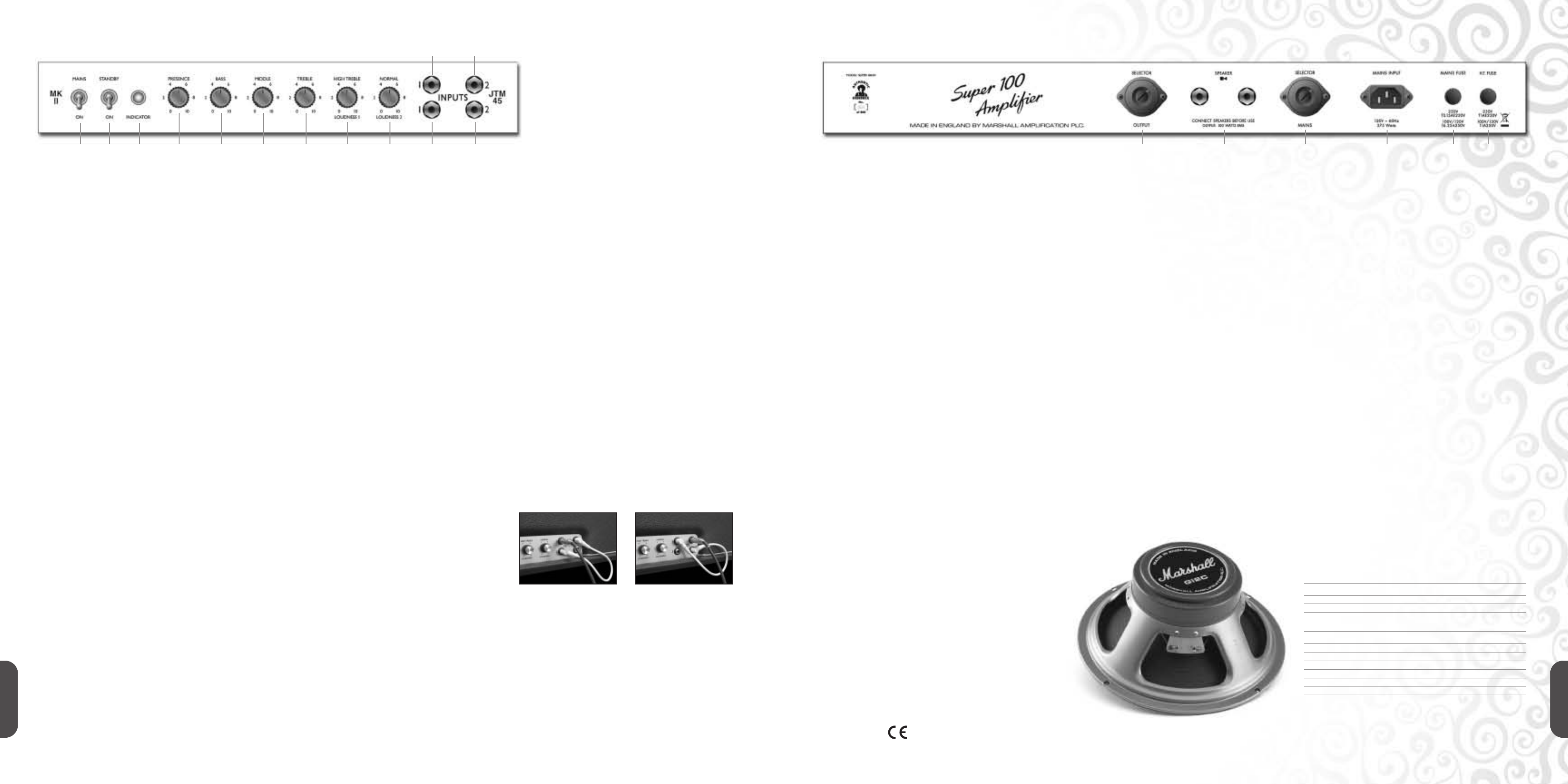
Speakers: Both of these 100 Watt, mono, cabs are loaded with
Celestion G12C 25 Watt Speakers which have been specially
developed by Marshall and Celestion to duplicate the smooth,
balanced sound of the original 25 Watt Greenback speakers
found in authentic reference cabinets. In keeping with that time
period, a black and gold Marshall label is on the back of the
magnet cover, ensuring the look is as authentic as the sound.
EUROPE ONLY - Note: This equipment has been tested and found to comply with the requirements of the EMC Directive (Environments E1, E2 and E3 EN 55103-1/2) and the Low Voltage Directive in the E.U.
EUR
OPE ONL
Y - Note:
The Peak Inrush current for the Super 100JH is 39 amps.
TECHNICAL SPECIFICATION
SUPER 100JH Head
Power Output 100W RMS
W
eight
22 kg
Size
741mm x 270mm x 210mm
1982AJH & 1982BJH Cabinets
Power Handling (per cabinet)
100W RMS
Impedance 16 Ohms per cabinet
Inputs Mono 1/4" jacks
Weight - 1982AJH 36.4 kg
Weight - 1982BJH 41.5 kg
Dimensions - 1982AJH
754mm x 741mm x 355mm
Dimensions - 1982BJH
754mm x 914mm x 355mm
Fig. 1 Fig. 2
1 2 3 4 5 6 7 8 9 11 13 1 2 3 4 5 6
10 12
“
They were his partners in crime. Of all the
amps he used, they were the most reliable,
packed the biggest punch and had the best tone.
”
Eddie Kramer