


9
8
ENGLISH
ENGLISH
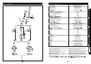
1. MAINS INPUT
Your amp is provided with a detachable
mains (power) lead that is connected here.
The specific mains input voltage rating that
your amplifier has been built for is clearly
marked on the back panel. Before connecting
for the first time, please ensure that your
amplifier is compatible with your electricity
supply. If you have any doubts, please get
advice from a qualified person.Your Marshall
dealer can help you in this respect.
2/3. SPEAKER OUTPUTS
The MODE FOUR Head has two speaker
sockets for connection to either 1 or 2 external
cabinets.
Always use a non-screened Marshall
approved heavy duty speaker lead when
connecting an extension cabinet to these
units.
Please refer to Cabinet Options Section
(page 10), for full details on choice of
cabinet(s) and how to correctly connect them.
4. FOOTSWITCH
Connect the supplied six-way LED
footcontroller here. When the footcontroller is
connected you can select the amp’s four
modes by either the front panel switches or
the footcontroller. In addition to allowing you to
switch between the amp’s four modes –
CLEAN, CRUNCH, OD1 and OD2 – the
footcontroller also facilitates REVERB on/off
and SOLO on/off switching.
NOTE: Always tighten the screws on each
end of the footcontroller’s cable to ensure
correct operation.
5. TUNER OUT
This where you connect the input of the
tuner you're using.
TONE TIP: For ‘silent’ tuning engage the
MUTE switch on the front panel (14).
6. LOAD PROTECTION CIRCUIT
ACTIVE LED
The MODE FOUR is designed to produce its
maximum rated power of 350 Watts into an 8
Ohm load.
Using a load of less than 8 Ohms could
damage the MODE FOUR and loudspeaker
cabinet.
If you use the MODE FOUR with a load of
less than 8 Ohms the LOAD PROTECTION
CIRCUIT will become active, there will no
longer be sound, and the LOAD
PROTECTION CIRCUIT LED will light (please
refer to the Cabinet Impedance Section -
page 10).
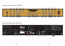
EFFECTS LOOP
(PARALLEL / SERIES)
To increase the flexibility of your MODE
FOUR even further you may choose to
connect external effects units to the built-in
Parallel to Series FX LOOP. The effects loop
allows direct connection of either floor pedals
(stomp boxes) or rack processors. The FX
LEVEL switch (8), provides the correct
operating level to match your external effects
device(s) (+4dB for rack units and -10dB for
pedals). The amount of the chosen effect you
add to AMP 1 and AMP 2 is determined by
their respective FX LEVEL controls.
Since the MODE FOUR’s FX LOOP is
parallel, it means that the direct (‘dry’) signal is
not passed through the loop and that your all-
important tone is not at risk of being degraded
by being sent through any external devices.
Only a relatively small amount of signal is sent
to the processor being used.
When either of the effects level controls are
turned up full, the FX LOOP of that AMP
becomes a Series Loop. This means that the
entire signal is sent through the loop.
FX LOOP TONE TIP 1: As a rule, effects
involving Distortion or Wah are not used in an
FX loop; they’re normally connected between
the guitar and amp. They were specifically
designed for use in front of the amp and, as a
result, sound best when used that way. Time
based effects such as Chorus, Flange, Reverb
and Delay are best suited for Parallel FX loop
use. This said remember, THERE ARE NO
RULES so if you think your Wah and Fuzz
pedals sounds best in the FX loop then go for
it!
FX LOOP TONE TIP 2: When using time
based effects such as Delay, Chorus, Flange
and Reverb in the FX LOOP, for optimum
performance the direct signal in the processor
should be set to zero so that only the effect
signal is returned to the amp. Doing this
ensures the most effective control of the effect
level (via FX LEVEL Control 11 & 24) and that
the tonal integrity of the amp’s direct (dry)
signal is unimpaired in any way by the
processor.
FX LOOP TONE TIP 3: When using an effect
such as Noise Reduction in the FX LOOP
you’re going to want it to work on the whole
signal so the FX LEVEL of each AMP should
be turned up full so that the loop becomes a
Series one.
FX LOOP TONE TIP 4: If you decide to use
a stomp box in the FX LOOP, unless the unit
has a Dry/Wet mix control (or is a stereo
device that has an output that only carries a
‘wet’ signal), in order to make the effect sound
its best you’re probably going to have to set
the FX LEVEL Controls on maximum, or very
close to it. Remember though, by doing this
you are putting the tonal integrity of the
MODE FOUR at risk because you’re sending
the entire signal through the effect box(s)
being used. Let your ears decide what’s good
and what’s not!
FX LOOP TONE TIP 5: Always use high
quality, screened patch cables . . . and the
shorter the better. Long cables can reduce top
end and overall punch.
FX LOOP TONE TIP 6: If the processor
being used has an input level control, ensure
that it is set correctly.
7. FX RETURN Jack
This is where you connect the output of the
external effects device you’re using. As
already stated, the amount of the chosen
effect you’ll hear on AMP 1 and AMP 2 will be
determined by how you set their respective FX
LEVEL controls on the front panel.
8. FX LEVEL Switch
This switch allows you to select the correct
operating level for the effects unit you’re using.
As a rule the +4dB setting (switch in) is for
rack devices and the –10dB setting (switch
out) is for pedals (stomp boxes).
9. FX SEND Jack
This is where you connect the input of the
external effects device you’re using.
RECORDING / D.I.
OUTPUTS
10. EMULATED LINE OUTPUT Jack
and XLR
Thanks to our critically acclaimed speaker
emulation circuitry, the line level signal these
outputs carry is perfect for both live and studio
applications. As the EMULATED LINE OUT
circuit is pre-MASTER Volume, it means it still
operates when the MODE FOUR’s MASTER
volume control is turned all the way down –
making ‘silent’ recording possible. The signal
from both of these sockets is muted when the
TUNER MUTE switch (14) is engaged.
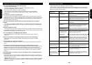
MODE FOUR Rear Panel Features - see panel page 70