


Channel Selection
The amplifier has 4 channels - Clean, Crunch, OD1 &
OD2.
Pressing the Clean/Crunch switch (3) selects between
the Clean (Green Light) and Crunch (Red Light)
channels.
Pressing the OD switch (5) selects between the OD1
(Green Light) and OD2 (Red Light) channels.
When moving from an OD channel to a Clean/Crunch
channel, the unit remembers the last channel you were
in before leaving. E.g. If you have moved from the
Crunch Channel to an OD channel and you press the
Clean/Crunch switch (3), the amplifier will revert back to
the Crunch channel - rather than starting again in the
Clean channel.
Modes
The amplifier operates in two modes - Preset and
Manual.
To change between these two modes, you must hold
the Damping switch (17) down for at least two seconds.
When in manual mode the Store switch (19) lights red
and the selected channel light (3 or 5) will start to flash.
The amplifier will remember the last mode it was in after
power off and revert to it the next time it is powered on.
Preset
This is the factory default operation of the amplifier.
In Preset mode the position of all controls except
Master Volume (16) are stored within each channel.
Each channel should be considered a preset.
Selecting a channel automatically recalls the settings
stored within the channel. Note: The physical position of
the front panel controls, except Master Volume (16)
which is not storable, will now not match the actual
settings of the unit. All front panel switches will
automatically update.
Altering a control will cause the associated parameter to
jump to the current physical position of that control.
When a control is altered the selected channel light (3
or 5) will start to flash indicating that the current preset
has been altered.
To store the updated settings, push the Store switch
(19).
If you select another channel without pressing Store
(19) then any altered settings will be lost as the new
channel and its settings are recalled.
Manual
In manual mode the amps settings always match the
physical positions of the controls.
Changing channel only changes the channel, NO
presets are recalled, NO other controls are altered.
Pressing Store (19) will store the current settings into
the selected channel. These can then be recalled when
using the unit in Preset mode.
When channel settings have been stored the current
channel light (3 or 5) will stop flashing indicating the
preset has been saved.
Reverb & FX
The amplifier provides three simultaneous effects,
Reverb, Delay and one of three Modulation effects
(Chorus, Phaser, or Flanger).
Reverb
The Reverb control sets the amount of signal sent to
the reverb section - allowing the reverb to spill between
channels as different presets are recalled. The Rev
switch (8) switches the reverb effect on and off, the
status of the reverb is also indicated on the
footcontroller.
FX
The FX section consists of two effects, Delay and
Modulation. The FX section can be globally turned on
and off via the FX switch (11).
Delay
The Delay control (14) sets the amount of signal sent to
the delay section. When the Delay control (14) is set to
‘0’ the delay is switched off.
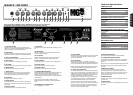
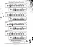
Modulation
The Mod control (12) is split into three segments and
selects the type of modulation effects and adjusts its
associated settings. When the Mod control (12) is set to
‘0’ the modulation effects are switched off.
Tap Tempo
The Tap Tempo switch (13) is used for the Delay effect
only.
The Tap Tempo switch matches the delay time to the
time between two presses.
The Tap Tempo LED flashes red at the
selected/recalled delay time.
The number of repeats is reduced as the delay time
decreases.
If you change from a channel with delay to one without
delay the effect will spill between channels.
If you change from a channel with delay to a channel
with delay set to a different delay time the delay effect
will not spill between channels.
MP3 / Line In
The 3.5mm MP3 / Line In socket (24) on the rear panel
allows the connection of an external audio source e.g.
MP3 or CD player.
76
Headphones & Line Out
The 3.5mm Headphones socket (18) allows the
connection of a pair of headphones. When a jack is
inserted into the headphones socket the unit’s speaker
is muted.
Additionally the Headphones socket (18) can also be
used as a Line Out to send the signal to an external
equipment e.g. A computer, digital recorder or mixer.
When a jack is inserted into the socket the unit’s
speaker is muted providing ‘silent recording’. The unit’s
output can then be monitored directly from the external
equipment used.
Damping
The Damping switch (17) selects between the two
modes of power amp damping. When Damping is off
(LED off), the power amp response resembles the feel
of a classic power amp with emphasized middle and
limited bass and treble. Switching Damping on (LED on)
will boost the speaker resonances both in the bass and
high frequency ranges.
FX Loop
The FX Return socket (25) on the rear panel is used to
connect the OUTPUT of the effects processor or pedal
you are using in the effects loop.
The FX loop is series and set at instrument level so
both guitar FX or professional units can be connected.
The FX Send socket (26) on the rear panel is used to
connect to the INPUT of the unit you are using in the
effects loop.
The FX loop is switched on and off via the Ext FX
switch (15) on the front panel.
Loudspeaker
ALWAYS USE A NON-SCREENED MARSHALL
APPROVED SPEAKER LEAD WHEN CONNECTING
AN EXTENSION CABINET TO THESE AMPLIFIERS.
MG50FX
The single Loudspeaker socket (22) is used to connect
either the internal speaker or an external speaker
cabinet to the unit’s power amp. When using external
cabinets ensure the total load impedance is equal to, or
exceeds, 8 ohms.
MG100FX 1x12" & 2x12" Combos
The single Loudspeaker socket (22) is used to connect
either the internal speaker or an external speaker
cabinet to the unit’s power amp. When using external
cabinets ensure the total load impedance is equal to, or
exceeds, 4 ohms.
MG100HFX Head
The two Loudspeaker sockets are used to connect to 1
or 2 external cabinets. When using external cabinets
ensure the total load impedance is equal to, or exceeds,
4 ohms.
Power
The Power switch (20) turns the amplifier on and off. If
current settings have not been stored they will be lost.
Restoring Settings - WARNING: ALL AMP &
FOOTSWITCH SETTINGS WILL BE LOST
To restore the unit to factory settings (see handbook
rear cover) you must hold the Store switch (19) while
powering on the amplifier. The Clean/Crunch (3) and
OD (5) lights will light orange. You can then release the
Store switch (19).
Resetting the amplifier will erase all user Channel
presets and all user Footcontroller settings, replacing
them with the factory presets.
0
Chorus
Phaser
Flanger
Modulation Off
Speed increases and depth is reduced as
knob is turned clockwise.
Speed increases as knob is turned
clockwise.
Speed increases, feedback and depth are
reduced as knob is turned clockwise.
MG50FX & MG100FX / MG100HFX Overview
ENGLISH
* EUROPE ONLY - Note:
This equipment has been tested and found to comply with the requirements of the EMC Directive
(Environments E1, E2 and E3 EN 55103-1/2) and the Low Voltage Directive in the E.U.
* EUROPE ONLY - Note:
The Peak Inrush current for the MG50FX is 9.6 amps.
The Peak Inrush current for the MG100HFX, MG101FX and MG102FX is 21 amps.
Note:
This equipment has been tested and found to comply with the limits for a Class B digital device, pursuant to part 15 of the FCC rules.
These limits are designed to provide reasonable protection against harmful interference in a residential installation. This equipment generates,
uses and can radiate radio frequency energy and, if not installed and used in accordance with the instructions, may cause harmful interference
to radio communications. However, there is no guarantee that interference will not occur in a particular installation. If this equipment does cause
harmful interference to radio or television reception, which can be determined by turning the equipment off and on, the user is encouraged to try
to correct the interference by one or more of the following measures:
*
Reorient or relocate the receiving antenna.
*
Increase the separation between the equipment and the receiver.
*
Connect the equipment into an outlet on a circuit different from that to which the receiver is connected.
*
Consult the dealer or an experienced radio/TV technician for help.
Follow all instructions and heed all warnings
KEEP THESE INSTRUCTIONS !