


15
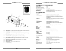
4. Microphone Operation
a. Turn on The Link 2 by sliding the ON/STANDBY/OFF SWITCH (37) to the STANDBY
position (transmitter on, audio muted) or the ON position (transmitter and audio both on).
The LOW BATTERY INDICATOR LED (36) will give a single quick flash, indicating
usable battery strength. In case of dead or low battery, the indicator will either not go on at all
or stay on continuously, indicating a battery voltage below 7V. If this occurs, replace with a
fresh 9V battery. Remember to turn the transmitter off when not in use.
b. The Link 2 is now ready to use. The AF DISPLAY LEDs (9) on the 401 receiver should
now be lit, indicating a received signal from the transmitter. When ready to speak, slide the
transmitter switch to the ON position and adjust the volume of the receiver as per the Audio
Output Microphone Connection section of the above 401 receiver instructions. The AF
LEVEL LED DISPLAY (9) on the 401 receiver will light up to 5 LEDs (4 green and 1 red)
for all input signals. Occasional flickering on and off during use of the top red LED indicator
in this display is normal, however if the red LED stays on continuously, it means the signal is
too loud and there is the possibility of overload distortion. Re-position the microphone farther
from the source or adjust the Link 2 transmitter gain with the VOLUME LO/HI GAIN
SWITCH (35). Set for the maximum possible level without noticeable distortion on the high
level peaks. Set the GAIN SWITCH to LO to decrease the audio level, and set the GAIN
SWITCH to HI to increase the audio level. The red LED indicator should flicker only on the
loudest inputs.
[Note: Observe care in selecting P.A. volume, transmitter location and speaker placement so
that acoustic feedback (howling and screeching) will be avoided. Please also observe the
pickup patterns of the microphone selected: omnidirectional mics pick up sound equally from
all directions and are prone to feedback if not used carefully. Unidirectional mics are more
resistant to feedback, but pick up sound sources best that are directly in front of the mic.
Also, mics that are farther from the sound source, such as lavaliers, require more acoustic
gain and thus are also more prone to feedback than close-source mics such as handheld or
headworn mics that are used close to the mouth.]
(Note: Microphone elements can easily be destroyed by the buildup of salts and minerals from
perspiration and saliva. It is good practice to put a windscreen on the mic element at all
times to protect it.)
OPERATION
14
The LINK 2
TM
Plug-In Transmitter
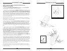
1. Transmitter Set-Up
First, slide open the BATTERY COMPARTMENT DOOR (39) to expose compartment.
Insert a fresh 9V ALKALINE BATTERY (41), observing polarity. Close the battery com-
partment door.
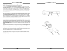
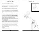
2. Handheld Microphone Installation
• Step 1 - Rotate the transmitter’s threaded LOCKING RING (33) clockwise toward
the XLR CONNECTOR (32) until it stops.
• Step 2 - Hold your mic in one hand and The Link 2 in the other.
• Step 3 - Plug your mic into the XLR CONNECTOR.
• Step 4 - Lock the mic into place with the adjustable threaded LOCKING RING by
rotating the ring, counterclockwise, to the top of the transmitter.
• Step 5 - To release the XLR CONNECTOR, turn the threaded LOCKING RING
clockwise and press the RELEASE BUTTON (40).
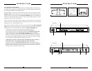
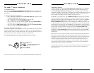
3. Lavalier Microphone Installation
The lavalier microphone you are using must terminate with an XLR connector and conform
to the pin assignments shown below. If they do not conform, you must use an appropriate
adapter or the lav mic may not work with the Link 2. If you have any questions, please con-
tact your Nady dealer or Nady Systems’ Customer Service Department.
Note: the pin assignments on The Link 2’s XLR connector are as shown:
XLR
Connector
Top View
3
12
Ground
Phantom Volt. (full 9V battery
voltage) switchable
Mic
Input
6.2K
6.5K
3
2
1
Note: Select phantom power, as needed, with the PHANTOM POWER ON/OFF SWITCH (38)
OPERATION
14