


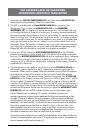

1. Rackmounting the Receiver
TherearetwooptionsavailableforrackmountingtheEncoreIreceiver:
singly or side‑by‑side with another Encore Series receiver.
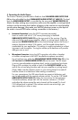
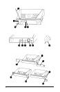
a. Single mounting: Remove the receiver SIDE MOUNT CLIP (1) from each side of
the receiver (as shown) and slide in the optional ERM-12 RACK EARS (9).
b. Side-by-side double mounting: After removing the SIDE MOUNT CLIPS (1) from
bothEncorereceivers,jointhetworeceiverswiththeEJC-2 JOINING CLIP (10)
and attach the ERM-22 RACK EARS (12) as shown.
(Note: Do not mount the receiver in a rack directly above an amplifier or
other source of high heat — this could degrade the performance of the
Encore I. Always ensure adequate airflow and heat dissipation in any rack
configuration.)
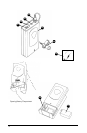
2. Powering the Receiver
Plug the 12V AC/DC ADAPTER (15) provided into the DC INPUT JACK (11) on
the back of the receiver. Then plug the power supply into an AC outlet.
(Note: Any 12V DC source with 400mA capability can also be used.)
Press the POWER SWITCH (8) once to turn on the receiver. The POWER ON LED (7)
will now light and the receiver is operational.
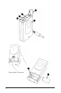
3. Antenna
The Encore I receiver is supplied with a TELESCOPIC ANTENNA (16). This should
beextendedfullytoobtainmaximumrange.Optimalantennapositionisvertical.
Formaximumrange,itisalwaysbesttomaintainalineofsight(noobstructions)
between the receiver antenna and the transmitter at all times whenever possible.
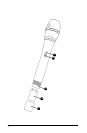
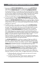
4. Mute (Squelch) Adjustment
In normal operation, the MUTE CONTROL (2) should be set fully counterclockwise to
the factory preset minimum RF level. However, in areas of high RF activity, the mute
(orsquelch,asitissometimescalled)mayneedtobeadjustedtocompensateforthe
adverse conditions in a particular location. If, with the transmitter off, one or more
LEDs of the 5 LED RF LEVEL DISPLAY (4)ickerorstayon,thesquelchcontrolshouldbe
turnedclockwiseuntiltheLEDsextinguish.Whenthesquelchisproperlyadjusted,
the RF LEVEL LED displays will only light when the system transmitter is turned on.
Turning the squelch control too far clockwise will reduce the range, but yield a
quieter mute (squelch) function. When the 5 LED RF LEVELdisplayextinguishes,the
transmitter is out of range for that given location, and the user should move closer to
the receiver to re‑establish the radio link.
4
ENCORE I RECEIVER