


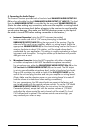
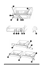
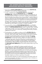

1. Rackmounting the Receiver
TherearetwooptionsavailableforrackmountingtheEncoreIIreceiver:
singly or side‑by‑side with another Encore Series receiver.
a. Single mounting: Remove the receiver SIDE MOUNT CLIP (1) from each side of
the receiver (as shown) and slide in the optional ERM-12 RACK EARS (9).
b. Side-by-side double mounting: After removing the SIDE MOUNT CLIPS (1) from
bothEncorereceivers,jointhetworeceiverswiththeEJC-2 JOINING CLIP (10)
and attach the ERM-22 RACK EARS (12) as shown.
(Note: Do not mount the receiver in a rack directly above an amplifier or
other source of high heat — this could degrade the performance of the
Encore I. Always ensure adequate airflow and heat dissipation in any rack
configuration.)
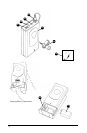
2. Powering the Receiver
Plug the 12V AC/DC ADAPTER (15) provided into the DC INPUT JACK (11) on
the back of the receiver. Then plug the power supply into an AC outlet.
(Note: Any 12V DC source with 400mA capability can also be used.)
Press the POWER SWITCH (8) once to turn on the receiver. The POWER ON LED (7)
will now light and the receiver is operational.
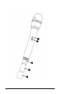
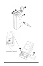
3. Antennas
The Encore II receiver is supplied with TELESCOPIC ANTENNAS (16). These should be
extended fully to obtain maximum range. Optimal antenna position is 45 degrees
fromthereceiver(at90degreesfromeachother).Formaximumrange,itisalways
best to maintain a line of sight (no obstructions) between the receiver antennas and
the transmitter at all times whenever possible.
4. Mute (Squelch) Adjustment
In normal operation, the MUTE CONTROL (2) should be set fully counterclockwise to
the factory preset minimum RF level. However, in areas of high RF activity, the mute
(orsquelch,asitissometimescalled)mayneedtobeadjustedtocompensateforthe
adverse conditions in a particular location. If, with the transmitter off, the receiver’s
A and/or B DIVERSITY LED INDICATORS (3) and/or one or more LEDs of the 5 LED RF
LEVEL DISPLAY (4) ickerorstayon,thesquelchcontrolshouldbeturnedclockwise
untiltheLEDsextinguish.Whenthesquelchisproperlyadjusted,theAand/orB
LEDs or the RF LEVEL LED displays will only light when the system transmitter is turned
on. Turning the squelch control too far clockwise will reduce the range, but yield a
quieter mute (squelch) function. During operation, especially at ranges greater than
75feet,oneortheotheroftheAorBLEDsmayextinguishbriey.Thisisnormal—
the unit’s DigiTRU Diversity
™
reception ensures that the received audio will not be
interrupted. When both the A/B DIVERSITY LEDs and the 5 LED RF LEVEL display
extinguish, the transmitter is out of range for that given location, and the user should
move closer to the receiver to re‑establish the radio link.
4
ENCORE II RECEIVER