CONTROLS AND CONNECTIONS
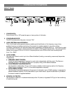
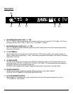
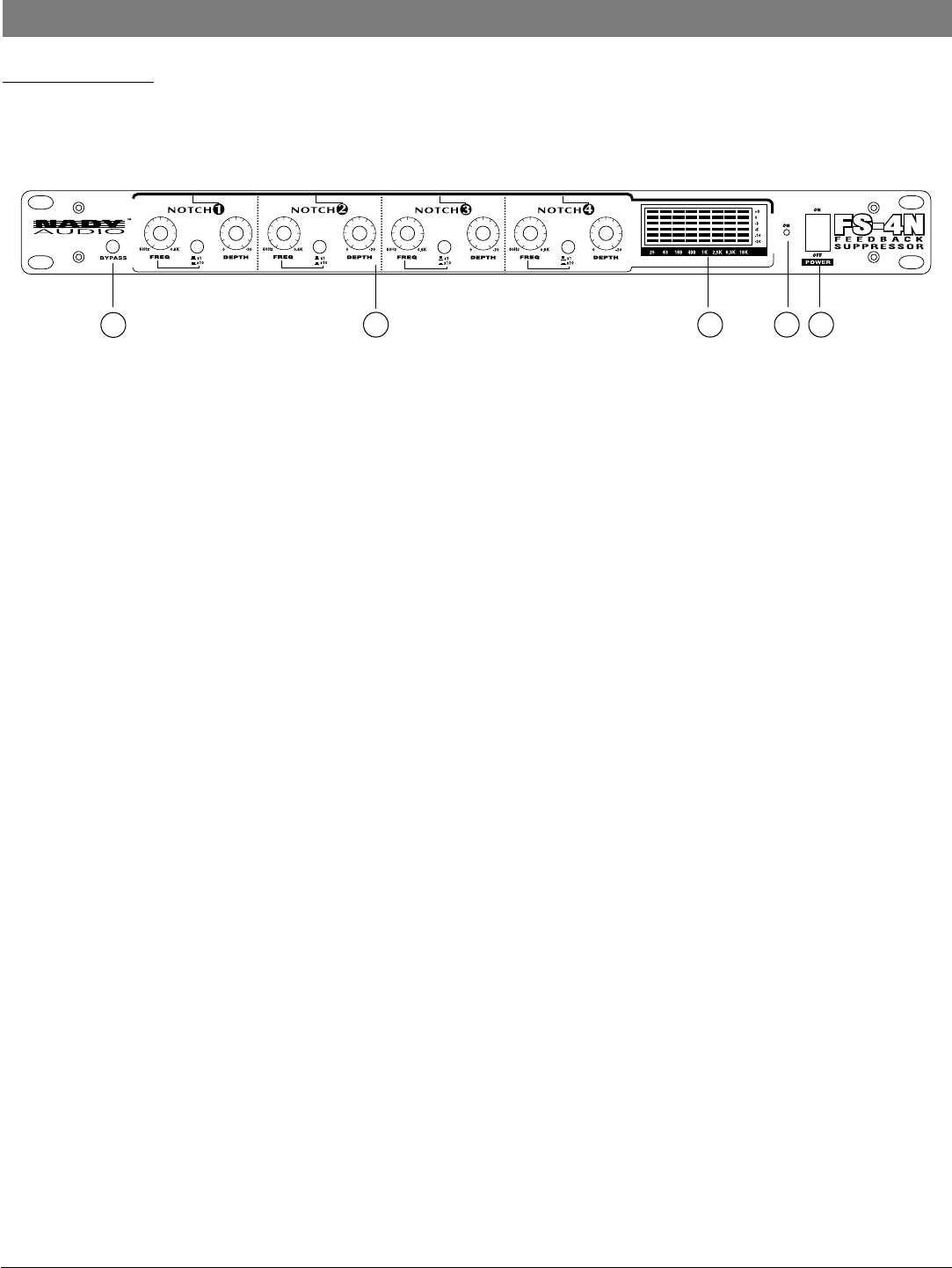
FRONT PANEL
1. POWER SWITCH
To turn the unit ON or OFF, press the upper or lower portion of this button.
2. POWER LED INDICATOR
This LED illuminates when the power is turned "ON".
3. AUDIO SPECTRUM ANALYZER DISPLAY
This in-line 8-band audio spectrum analyzer enables quick identification of the frequency range of any
problem frequency and allows monitoring of the amount of reduction selected in any of the notches.
The display monitors both the input and output levels as selected by the Bypass switch (5). It monitors the output
when the switch is IN (down), and the input when the switch is OUT (up) for bypass mode. The audio spectrum
display has a range of 25Hz to 16 KHz in 8 frequency bands, with 6 LEDs in each tree indicating levels
from +3 to –20dB.
4. NOTCH FILTERS
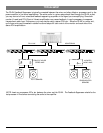
Use these notch filters to control up to four different feedback (howling or screeching resonances) frequencies
independently.
a. FREQUENCY SELECT CONTROL
Adjust the desired suppression frequency for each notch independently with this control. The filters are
extremely narrow (1/60 octave) so take care in properly tuning out the desired feedback.
b. SCALE FREQUENCY MULTIPLIER SWITCH
Use this switch to select either X1 (up) or X10 (down) multiplier of the frequency scale on the Frequency
Select Control as needed to "tune in" on the desired suppression frequency.
c. NOTCH DEPTH CONTROL
Use this control for precise adjustment of the amount of attenuation (up to -20dB) necessary to suppress the
selected feedback frequency. For the least effect on your overall sound, adjust the attenuation to just below
the amount needed to suppress feedback.
5. BYPASS IN/OUT SWITCH
Use this switch to select all 4 notches simultaneously either IN (down) or bypassed OUT (up) for fast monitoring
of results during use.
5
4 3 2 1
5


