


12
5
INSTALLATION
1. The IRW-2PA lockbox should be positioned in the room while considering the
following criteria:
• IR Sensors should be placed on either side of operating area and as close to
microphone operating area as possible. All rules of sensor installation should
be observed as per instructions 2 below.
• IRW-2PA can be easily connected to AC power.
• IRW-2PA optional features such as Aux input and hard-wired mic input can be
easily used as desired.
• IRW-2PA LED indicators can be viewed with ease.
• If placing the IRW-2PA on a table or shelf, it should be securely fastened so
that it cannot fall over or cause any damage if the transmitters accidentally fall
when inserted or removed from the case.
• If hanging on the wall, the IRW-2PA should be properly secured to a strut or
solid wall at a reasonable height (no more than 65” from the oor).
• Installation should be performed by qualied personnel using proper
hardware to ensure there is absolutely no risk of the unit falling or causing
damage of any kind.
(Nady Systems is not liable for any damage or harm caused due to improper
installation or use of this product. All installation should be done by qualied
personnel only)
2. The IRW-1S sensors can be mounted on walls using any of the wall mounts
included. To ensure proper optimum operation, observe the following installation
rules:
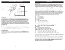
a. Position the IR Sensors with their front panel receptors facing the entire area
of transmitter operation. If this is a wide area, angle the receptors to cover the
maximum area range. The diagrams on the opposite page shows some suggested
positioning for the IR Sensors.
Note: The IR sensors will need to be positioned differently for each environment.
During installation, power up the IRW-2PA and have one person walk around the
desired location, with the transmitters on, while another person positions the IR
Sensors for greatest range of mobility.
b. Since the unit utilizes infrared light reected off of room surfaces, do not mount
the sensors near a black ceiling, wall, or heavy curtains as they may limit the range
by eliminating such reection. Mounting the sensors in an uncluttered area near a
light colored wall will provide the best operation.
c. Although the unit can be used in most brightly lit rooms, it works best if bright
lights are not shined directly on the sensors. (Note: Never operate the unit outdoors
in daylight as it will not operate properly under such conditions)
d. Never cover the IR Sensors as this will disrupt normal operation. If they become
dirty, clean with a soft cloth. Make sure the sensors are not obstructed and always
have a clear line-of-sight with the transmitters.
Additional external IR sensors can be added using the IRW-SY Multiple Sensor Y-
adapter which allows multiple sensors to be connected to each input.
See diagrams for some examples of installation (next page).
WARNING: MAKE SURE ALL POWER IS OFF TO THE IRW-2PA WHEN
CONNECTING OR DISCONNECTING THE IRW-1S IR SENSORS TO AVOID
DAMAGE TO THE UNIT. IMPROPER OPERATION WILL VOID THE WARRANTY
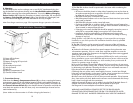
3. Charging
The IRW-2PA can be used to recharge one or two HT-6SC simultaneously by plac-
ing the handheld microphones directly into the Handheld Microphone Holders
(12) without removing the rechargeable batteries. Turn on the Battery Charging
Power Switch (14). When the microphone is placed in the holder, the correspond-
ing Battery Charging LED Indicator (15) on the IRW-2PA will light brightly red.
The LED indicator will light green when the batteries are fully charged.
Note: See charger section on page 9 for important charger operation information.
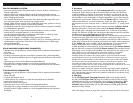
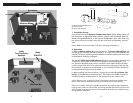
HT-6SC HANDHELD MICROPHONE TRANSMITTER
(1) Power LED Indicator
(2) Power Switch
(3) Battery Charging DC Input Jack
(4) IR Emitter
(5) Microphone Input Jack
(6) Volume Control
(7) Belt Clip
(8) Battery Compartment Cover
(9) Channel Selector Switch
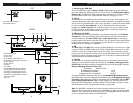
LT-6SC BODYPACK TRANSMITTER
(1)
(5)
(2)
(9)
(8)
(4)
(6)
(7)
1. Transmitter Set-up
Slide down the Battery Compartment Cover (8), as shown, exposing the battery
compartment. Insert 2 fresh AA alkaline batteries, NiMH rechargeable batteries, or
the optional IR-BBP battery pack while observing the correct polarity as marked. Set
the Channel Selector Switch (9) to the desired channel of operation and slide the
cover back into position on the unit. Note, only one transmitter per channel can be
used simultaneously.
(Note: Make sure the transmitter is off when changing the batteries.)
(3)