


5
CONTROLS AND CONNECTIONS
(1)
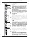
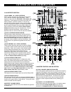
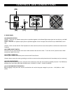
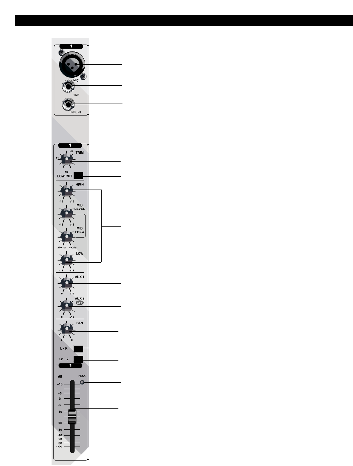
1. CHANNEL SECTION
(1) MIC INPUT
This electronically balanced XLR input is designed to accept signals from any
balanced or unbalanced low impedance (Low Z) microphone. To accommodate
condenser microphones, this input is also equipped with +48VDC phantom
power globally switchable to all XLR input jacks with the Phantom Power
Switch (27). Dynamic or ribbon-type microphones do not require phantom
power. The XLR jack is configured for: Pin1 = ground, Pin2 = positive (+), Pin3
= negative (-). The Mic inputs are more sensitive than the Line inputs. It will
be necessary to adjust the channel gain with the input Trim Control (4) to
achieve a nominal operating level.
[Note: Do not connect mics when phantom power is already switched on, as
indicated by the Phantom Power LED (27) in the Master Section of the top
panel. Never use unbalanced mic cables with the Phantom Power switched on.
Never short the +48VDC to ground, as that can cause serious damage to your
mixer. Also, turn down the Master Stereo Volume Faders (24) to prevent
possible sharp transient noise from damaging the speakers when turning the
phantom power on or off.]
(2) LINE INPUT
This 1/4” input is designed to accept balanced or unbalanced line-level signals
such as those from keyboards, drum machines, or samplers. There is enough
gain available on the line input to accept even lower level signals, such as
those from an unbalanced microphone or guitar output. If a balanced signal is
to be connected to the line input, then a 1/4” TRS (stereo) phone plug should
be wired for: Tip = positive (+), Ring = negative (-), Sleeve = ground.
[Note: Only the Mic or the Line input of a given channel should be connected at
one time. Do not connect both at the same time.]
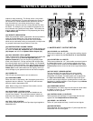
(3) INSERT
All channels are equipped with insert jacks to connect external signal
processors such as compressors, noise reduction systems, or effects devices
to the individual input channels. Insert points are useful for adding dynamic
processing or equalization to a channel or the mix. Unlike reverbs, etc., which
are usually added to the dry signal, dynamic processing is normally applied
across an entire signal. Here an Aux Send would be inappropriate. Instead, the
signal is intercepted somewhere along the channel, fed through the dynamics
processor and/or EQ, and then returned to the console at the same point where
it left. The insert point is normalized, i.e., the signal is only interrupted when a
plug is plugged into it. To use Inserts as a Send/Return, an insert cable is
required which will split the 1/4” TRS insert connection to two plugs, one for
Send and one for Return. The insert jack is pre EQ in the channel and is
configured as: Tip = send, Ring = return, Sleeve = ground.
The Insert can also be used as a channel direct output by sending the signal
from the ring. To use the Insert as a direct output, insert a 1/4” phone plug
halfway into the Insert jack so the tip of the plug connects with the ring of the
insert jack. The jack will click into place when the connection to the ring is
made.
(4) TRIM CONTROL
The Trim control adjusts the input sensitivity (channel gain) of the Mic and Line
inputs on the channels. This control can be adjusted to accommodate input
signals from a wide variety of sources, from the high outputs from keyboards or
drum machines to the small signal outputs of microphones. The trim control
adjusts the input sensitivity with 30dB of range. The best balance of S/N and
dynamic range will be achieved if you adjust the TRIM control on each channel
separately so that the Channel Peak LED (5) for that channel almost lights.
(2)
(3)
(4)
(5)
(8)
(9)
(10)
(11)
(12)
(13)
(6)
(7)