


7
CONTROLS AND CONNECTIONS
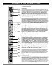
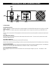
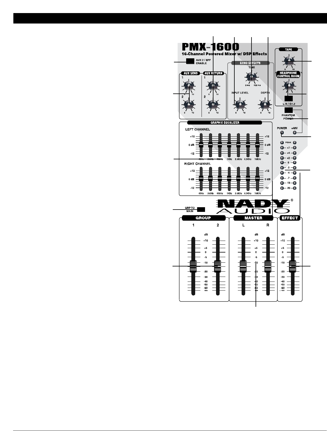
2. AUX EFFECTS SECTION
(14) AUX SEND 1 & 2 LEVEL CONTROLS
These controls adjust the final mixed level of the channel
Aux 1 and Aux 2 auxiliary signals separately. These
signals are then sent to the Aux Send 1 & 2 Outputs (30)
respectively. These signals can be sent to the input of an
effects processor, multi-track recorder, or used for any
other line-level auxiliary purpose, such as monitor feeds. If
the signal is going to be used for an external reverb/delay
device, preferred instead of the internal Echo Effects, Aux
Send 2 should be used and the Aux 2 / Effects Enable
Switch (15) should be set to Aux 2 (button out). This will
disable the internal Echo Effects. When the switch is
depressed, the Aux 2 level control and output are disabled.
(15) AUX 2 / EFFECTS ENABLE SWITCH
This push button switch determines if the Channel Aux 2
Eff Send signals are sent to Aux Send 2 (button out) or to
the internal Echo Effects section (button depressed). The
Aux 2 Level Control (16) and output are disabled when
this button is set to enable the internal Echo Effects. Note
the Aux Return 2 is operational regardless of this switch
setting.
(16) AUX RETURN 1 & 2 LEVEL CONTROLS
These controls adjust the signal level from the Aux Return
1 & 2 Inputs, which are then mixed into the Left and Right
Master bus. These can be used to return effected signals
into the PMX Series powered mixer or they can be used
as auxiliary inputs from line level devices such as
keyboards or Tape Returns of multi-track recorders. The
internal Echo Effects cannot be applied to these auxiliary
returns. Note, Aux Return 2 is operational regardless of
the Aux 2 / Effects Enable Switch (15) setting.
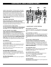
(17) ECHO EFFECTS TIME DELAY
This control sets the time interval, in milliseconds, of the
built-in Echo Effects DSP (Digital Sound Processor). Lower
settings select the shortest echo time to emulate plate
effects whereas higher settings enable the longest echo time for
stadium reverbs and delay sounds with up to 200mS delays.
Settings around 100mS emulate medium room and hall reverbs
by adjusting the channel Effect Control (9) and Echo Depth
(19) to nine o’clock, Echo Input Level (18) to 12 o’clock, and
Effect Volume Fader (20) to approximately -10dB.
(18) ECHO EFFECTS INPUT LEVEL
This adjusts the level of signal input into the Echo Effects DSP.
(19) ECHO EFFECTS DEPTH
This control adjusts the number of repeats and feedback/depth of
the echo effect. Turning the control clockwise sets the repeats to
maximum for lengthy echoes or plate effects. Turning the control
counter-clockwise sets less repeats.
(20) EFFECT VOLUME FADERS
These faders adjust the final level of the effected tone applied to
the Master bus.
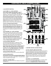
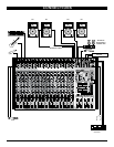
3. MASTER CONTROL AND EQ SECTION
(21) DUAL CHANNEL GRAPHIC EQUALIZER
The 7-band graphic equalizers allow you to adjust the frequency
response of the Master L and R mix providing a maximum of +/-
12dB of cut and boost for each frequency band from the center
détente flat position. The top EQ is for the Left channel and the
bottom EQ is for the Right channel. This EQ can be used to
shape and mold the tone of your audio and easily eliminate
feedback at notch frequencies without overly affecting your
sound.
(22) GROUP 1 & 2 VOLUME FADERS
These faders adjust the level of the Group 1 & 2 submix signals
that are sent to the Group Outputs (35) and can also be
selected for the Headphone (33) and Control Room (34)
(17)
(21)
(22)
(24)
(23)
(25)
(26)
(27)
(29)
(28)
(14)
(15)
(16)
(20)
(19)
(18)