


7
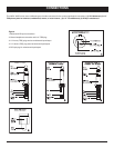
FRONT CONTROLS AND CONNECTIONS
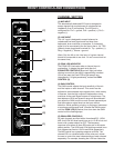
MASTER SECTION
(10) POWER ON/OFF SWITCH
This switch turns the unit on and off. The SPM-4250 uses
relays to ensure quiet turn-on and turn-off.
(11) 48V PHANTOM POWER LED
Lights to indicate when 48V phantom power is turned on.
(12) ECHO EFFECTS DISPLAY
This numeric Effects Display will indicate which of the 16
echo presets has been selected.
(13) ECHO TIME SELECT BUTTONS
Use these UP and DOWN buttons to select one of 16
preset time intervals of the built-in Echo Effects DSP
(Digital Sound Processor). Setting 1 selects the shortest
echo time to emulate plate and doubling effects whereas
setting 16 enables the longest echo time for stadium
reverbs and delay sounds. Settings around 4 - 7 emulate
room and hall reverbs by adjusting the ECHO DEPTH
CONTROL (14) to approx ten o’clock and the ECHO
LEVEL CONTROL (15) to mid.
(14) ECHO DEPTH CONTROL
This adjusts the number of repeats and feedback/depth of
the echo effect selected. Turning the control clockwise
sets the repeats to maximum for lengthy echoes or plate
effects. Turning the control counter-clockwise sets one
repeat for single delay or doubling effects.
(15) ECHO LEVEL CONTROL
This adjusts the level of the effected signal sent to the
master mix bus.
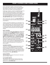
(16) 5-BAND GRAPHIC EQ
The 5-band graphic equalizer allows you to adjust the
frequency response of the left and right master bus signal,
allowing final tonal adjustments. This provides a maximum
of 12dB cut or boost from the flat position for each
frequency band; 63Hz/250Hz/1KHz/4KHz/12KHz. The
faders can be adjusted to easily eliminate feedback at the
corresponding frequency. These EQ’s are pre MASTER
VOLUME.
(17) LED OUTPUT METER
The 5-stage stereo output LED meter display the can be
used to maintain proper levels in the master mix. The red
PEAK LED will light when the output signal is just below
clipping. It is acceptable if the red LED lights occasionally.
If the red LED lights more than occasionally, you should
turn down the MASTER VOLUME (24) to avoid audible
distortion and clipping, which can cause damage to your
speaker and even the internal amplifier.
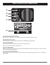
(18) AUX SEND JACK
The AUX SEND JACK provides a mono mixed signal
output from each input channel to an external effects unit
or other device. The signal level is adjusted by the EFF
and Volume controls of each channel.
(19) AUX RETURN
This input can be used to return the effected signal into the
SPM-4250 or it can be used as an auxiliary input for line
level devices. The input signal can be adjusted using the
MASTER VOLUME (24) and the output volume of the
external unit.
(20) TAPE INPUT / REC OUTPUT JACKS
The Left and Right TAPE INPUT RCA jacks allow cassette
recorders, CD players, or MP3 players to be added to the
master mix output. These signals are affected by the
TAPE LEVEL (21), MASTER VOLUME (24), and 5-BAND
EQ (16). The RECORD OUTPUT Left and Right RCA
jacks provides signal output to recording devices, home
audio equipment, or external amplifiers. These outputs are
post MASTER VOLUME and 5-BAND EQ.
(21) TAPE LEVEL
This adjusts the amount of TAPE IN signal that is sent to
the master bus.
(22) HEADPHONES CONROL AND JACK
This control and corresponding 1/4 output is for connecting
headphones to the SPM-4250 to monitor each channel, or
the master mix, dependant on the MASTER PFL (23)
setting.
(23) MASTER PFL SWITCH
When this push-button switch is out, the HEADPHONES
receive the main mix signal post 5-BAND EQ / pre-
MASTER VOLUME. When the button is depressed, the
signal is sent from each channel PFL control to the
HEADPHONES. In this setting, the HEADPHONES jack
can also be used as a sub-mix output.
(24) MASTER VOLUME
The MASTER VOLUME sets the level of the stereo signal
sent to the internal power amplifiers.