


CONTROLS AND CONNECTIONS
9
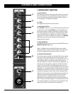
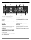
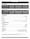
4. MASTER CONTROL SECTION
(19) (20) (21) (27)
(22) (23) (24) (25) (26)
(28) (29)
(19 & 22) AUX 1 AND 2 RETURNS CONTROLS
These are input controls that adjust the levels of the signal at the
AUX input jacks.
20) DSP/MIX
This is a master control that adjust the return of the DSP signals
that effect all channels.
21) AUX SEND
This is a master control that adjusts the output signal level at the
AUX SEND (30) jack.
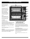
23) TAPE IN
This adjusts the amount of signal that is sent from the external
tape player connected to TAPE IN L,R (34,35) jacks.
24) MONITOR OUT
This adjusts the final level of the MONITOR bus. It affects both
the MONITOR output jack and output of the RIGHT/MONITOR
SPEAKER OUTPUT (37) jacks when PWR AMP MODE (25)
switch is in MAIN/MONITOR position.
25) POWER AMP MODE
The PWR AMP MODE switch allows you to select the signal that
will be output from the built-in dual channel amplifier: STEREO,
BRIDGE or MAIN/MONITOR MODE.
26) MAIN MASTER
This adjusts the final level of the MAIN bus signal that is sent to
the LEFT/MAIN SPEAKER OUTPUT (37), when PWR AMP
MODE (25) switch is in the MAIN/MONITOR position.
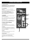
27) POWER LED
The red LED will illuminate when the unit is switched on.
28) PHANTOM POWER LED
The LED will illuminate when the PHANTOM POWER (29) switch
is depressed to ON.
29) PHANTOM POWER ON/OFF SWITCH
When this switch is depressed, +48V of phantom power will be
supplied to the mic channels.
(Note: When turning on the PHANTOM POWER (29) switch, turn
channel level to minimum.)