


5
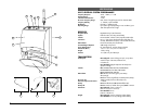
5. Connecting the Audio Output
The UHF-3 receiver provides both a fixed mic level BALANCED MIC AUDIO OUTPUT
XLR (7) and an adjustable line level AUX AUDIO OUTPUT 1/4" jack (10).
(Note: As when making any connection, make sure the amplifier or mixing board
volume is at the minimum level before plugging in the receiver to avoid possible
sound system damage.)
Microphone Connection
(using the UB-3 transmitter with either a headworn or lavalier microphone or the
UH-3 handheld microphone transmitter) For microphone use, either the BALANCED
MIC AUDIO OUTPUT XLR (7) or the 1/4" line level AUX AUDIO OUTPUT (10) can be
used. The XLR output is set at a non-adjustable microphone level, similar to hardwired
mic levels. Plug an XLR connector into the XLR output socket on the rear of the unit
and plug the other end into your amplifier or mixing board. Make sure the phantom
power on your mixing board is turned off and the volume is turned down when
making connections. For your convenience, the XLR output level is preset at the
factory and is not adjustable with the receiver volume control.
To use the 1/4" AUX AUDIO OUTPUT socket, follow the instructions for the Instrument
Connection (above), except start the receiver volume at 1/2 MAX and adjust until the
volume level is optimal. If the volume control is set too high, you may overload your
mixer or amp.
The UHF-3 receiver is equipped with a 5 segment LED AF LEVEL DISPLAY (14).
Occasional flickering of the top AF Peak LED indicator on loud inputs to the
transmitter is normal. If this LED lights continuously, decrease the volume to the
transmitter or overload distortion may result.
4
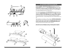
1. Rackmounting the Receiver
There are 2 options available for rackmounting the UHF-3 receiver: singly or side-by-
side with another UHF-3 Series receiver.
a. Single mounting: Remove the receiver SIDE MOUNT CLIP (1) from each side of
the receiver (as shown) and slide in the optional ERM-3 RACK EARS (2).
b. Side-by-side double mounting: After removing the SIDE MOUNT CLIPS (1) from
both UHF-3 receivers, join the two receivers with the EJC-3 JOINING CLIP
(3) and attach the ERM-33 RACK EARS (4) as shown.
(Note: Do not mount
the receiver in a rack directly above an amplifier or other source of high heat –
this could degrade the performance of the UHF-3. Always ensure adequate
airflow and heat dissipation in any rack configuration.)
2. Powering the Receiver
Plug the 12V AC/DC ADAPTER (5) provided into the DC INPUT JACK (9) on the back
of the receiver. Then plug the power supply into an AC outlet.
(Note: Any 12V DC
source with 400mA capability can also be used.)
Press the POWER SWITCH (11)
once to turn on the receiver. The POWER ON LED (12) will now light and the receiver
is operational.
3. Antennas
The UHF-3 receiver is supplied with TELESCOPIC ANTENNAS (15). These should be
extended fully to obtain maximum range. Optimal antenna position is 45 degrees
from the receiver (at 90 degrees from each other). For maximum range, it is always
best to maintain a line of sight (no obstructions) between the receiver antennas and
the transmitter at all times whenever possible.
4. Mute (Squelch) Adjustment
In normal operation, the SQUELCH CONTROL (6) should be set fully clockwise to the
factory preset RF level (Max. Sens.). However, in areas of high RF activity, the squelch
(or mute, as it is sometimes called) may need to be adjusted to compensate for the
adverse conditions in a particular location. If, with the transmitter off, the receiver’s A
and/or B DIVERSITY LED INDICATORS (13) flicker or stay on, the squelch control
should be turned counterclockwise until the A and/or B LEDs extinguish. When the
squelch is properly adjusted, the A and/or B LEDs will only light when the system
transmitter is turned on. Turning the squelch control too far counterclockwise will
reduce the range, but yield a quieter squelch (mute) function. During operation,
especially at ranges greater than 75 feet, one or the other of the A or B LEDs may
extinguish briefly. This is normal–the unit’s DigiTRU Diversity™ reception ensures that
the received audio will not be interrupted. When both LEDs extinguish, the transmitter
is out of range for that given location, and the user should move closer to the receiver
to re-establish the radio link.
UHF-3 RECEIVER