


4
Quick User Controls Guide
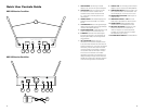
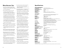
UWS-100 Receiver: Front View
1
SELECT
AF
A B
CHANNELIRASC
RF
A
B
UWS-100
UHF PLL WIRELESS SYSTEM
DigiTRU Diversity
™
ASC
™
SYSTEM
2 7 4 5 63
15VDC IN
400mA
MIC OUT
BALA NCED
UNBALANCED
LINE OUT
VOLUME
POWER
– +
MIN MAX
MUTE LEVEL
8 10 11 12 139
14
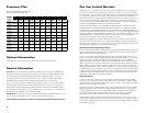
UWS-100 Receiver: Back View
5
1. DUAL ANTENNAS Permanently mounted.
Rotate to 45° as shown for optimal reception
2. SELECT BUTTON Press once quickly to start
the Auto Scan function to search for an
interference-free channel. Press and hold
for ~2 seconds to manually select one of
100 channels
3. CHANNEL DISPLAY LED indicator displays the
selected channel from 00-99 in numerical
format
4. AF LED INDICATOR Bi-color LED (green/orange)
displays received audio level (orange indicates
maximum allowable audio level)
5. RF A/B LED INDICATORS Indicate diversity A or B
antenna reception when transmitter is on
6. IR WINDOW Transmits LED Infrared signal
for linking the receiver to the transmitter for
frequency downloads, with blinking IR LED
status indicator
7. ASC
™
SYNC BUTTON Starts the IR link
download of the receiver’s selected channel
to the transmitter. Position the transmitter IR
receptor window 6-12” away from the receiver
IR window, press the ASC button once and
wait one second for the receiver to respond.
The red LED inside the IR window will flash
twice within two seconds. If the IR data
download is successful, the transmitter LCD
display’s backlight will light and the receiver’s
RF A/B LED will also light, indicating reception
of the receiver signal from the transmitter
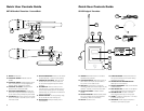
8. DC INPUT JACK For connecting external AC/DC
adapter to power receiver (DC15VDC/400mA)
9. POWER ROCKER SWITCH Press right side to turn
On or press left side to turn Off receiver. The
Channel Display (3) is lit when the unit is on
10. BALANCED MIC OUT XLR JACK Audio output at
fixed MIC level
11. UNBALANCED LINE OUT ¼” JACK Line level
audio output, adjustable with Volume control
12. VOLUME CONTROL Selects desired output
volume level for the Unbalanced Line Out
13. MUTE LEVEL (RF SQUELCH) Controls the mute
level for the receiver. Turn clockwise for
maximum range or turn counterclockwise,
if needed, to minimize noises from outside
RF interference upon muting
14. DC POWER SUPPLY ADAPTER DC15VDC/400mA