


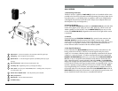

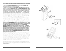

5. Connecting the Audio Output
The XR-61 receiver provides both a fixed mic level BALANCED AUDIO OUTPUT XLR (10)
and an adjustable line level UNBALANCED AUDIO OUTPUT 1/4” JACK (11). The level
from the UNBALANCED OUTPUT is controlled by the rear panel VOLUME CONTROL (12).
(Note: As when making any connection, make sure the amplifier or mixing board volume is
at the minimum level before plugging in the receiver to avoid possible sound system dam-
age. Also make sure that the phantom power on the input of the mixer is turned OFF
before making connection to the receiver.)
a. Instrument Connection (using the WGT-15 instrument transmitter)
Insert an audio cord with a 1/4” mono phone plug in the UNBALANCED OUTPUT
JACK (11) on the rear panel of the receiver. Plug the other end of the cord into an
amplifier, effects, or mixing board. Adjust the VOLUME CONTROL (12) on the XR-61
receiver clockwise to about 3/4 rotation, until the volume level is comfortable for your
application. This setting is roughly equivalent to a direct instrument cord connection.
Turning the volume up to maximum will provide 4dB gain over a cord.
b. Microphone Connection (using the WLT-15 transmitter with either a headset or
lavalier microphone or the WHT-15 handheld microphone transmitter)
For microphone use, either the BALANCED MIC AUDIO OUTPUT XLR (10) or the 1/4”
line level UNBALANCED OUTPUT (11) can be used. The XLR output is set at a non-
adjustable microphone level, similar to hardwired mic levels. Plug an XLR
connector into the XLR output jack on the rear of the unit and plug the other end
into your amplifier or mixing board. (Note: Make sure the phantom power on your
mixing board is turned off and the volume is turned down when making connections.)
For your convenience, the XLR output level is preset at the factory and is not adjustable
with the receiver volume control. To use the 1/4” UNBALANCED OUTPUT JACK (11),
follow the instructions for the Instrument Connection (above), except start with the
receiver volume at 1/2 MAX and adjust the volume control until the volume level is
optimal. If the volume control is set too high, you may overload your mixer or amp.
6
4. Microphone Operation
a. Turn on The Link 2 by sliding the ON/STANDBY/OFF SWITCH (41) to the STANDBY
position (transmitter on, audio muted) or the ON position (transmitter and audio both on).
The LOW BATTERY INDICATOR LED (40) will give a single quick flash, indicating usable
battery strength. In case of dead or low battery, the indicator will either not go on at all or
stay on continuously, indicating a battery voltage below 7V. If this occurs, replace with
fresh 9V battery. Remember to turn the transmitter off when not in use.
b. The Link 2 is now ready to use. The A and/or B DIVERSITY LED INDICATORS (8) and
most or all of the RF DISPLAY LEDs (9) on the XR-61 receiver should now be lit, indicating
a received signal from the transmitter. When ready to speak, slide the transmitter switch to
the ON position and adjust the volume of the receiver as per the Audio Output
Microphone Connection section of the above XR-61 receiver instructions. The AF LEVEL LED
DISPLAY (13) on the XR-61 receiver will light up to 5 LEDs (4 green and 1 red) for all
input signals. Occasional flickering on and off during use of the top red LED
indicator in this display is normal, however if the red LED stays on continuously, it means
the signal is too loud and there is the possibility of overload distortion. Re-position the
microphone farther from the source or adjust the Link 2 transmitter gain with the VOLUME
LO/HI GAIN SWITCH (39). Set for the maximum possible level without noticeable distortion
on the high level peaks. Set the GAIN SWITCH to LO to decrease the audio level, and set
the GAIN SWITCH to HI to increase the audio level. The red LED indicator should flicker
only on the loudest inputs.
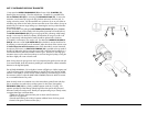
[Note: Observe care in selecting P.A. volume, transmitter location and speaker placement
so that acoustic feedback (howling and screeching) will be avoided. Please also observe
the pickup patterns of the microphone selected: omnidirectional mics pick up sound equally
from all directions and are prone to feedback if not used carefully. Unidirectional mics are
more resistant to feedback, but pick up sound sources best that are directly in front of the
mic. Also, mics that are farther from the sound source, such as lavaliers, require more
acoustic gain and thus are also more prone to feedback than close-source mics such as
handheld or headworn mics that are used close to the mouth.]
(Note: Microphone elements can easily be destroyed by the buildup of salts and minerals
from perspiration and saliva. It is good practice to put a windscreen on the mic element at
all times to protect it.)
15