


FP-AI-110 and cFP-AI-110 4 ni.com
is 2 A or less and the maximum current through any V
SUP
terminal
is 1 A or less.
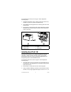
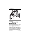
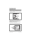
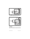
Install a 2 A maximum, fast-acting fuse between the external
power supply and the V terminal on each channel. The wiring
diagrams in this document show fuses where appropriate.
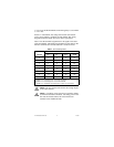
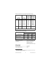
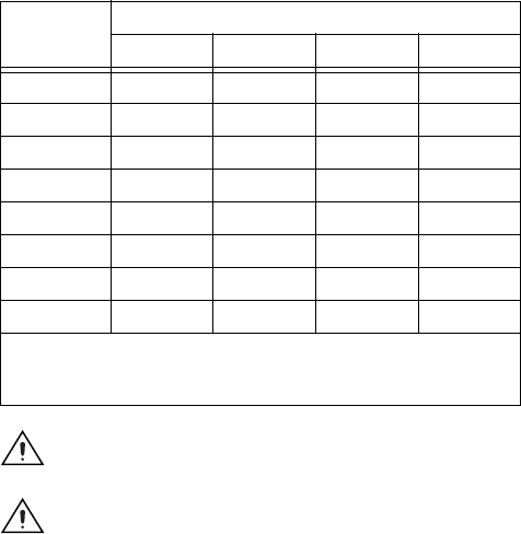
Table 1 lists the terminal assignments for the signals associated
with each channel. The terminal assignments are the same for the
FP-TB-x terminal bases and the cFP-CB-x connector blocks.
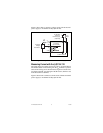
Caution Do not connect both current and voltage inputs
to the same channel.
Caution Cascading power between two modules defeats
isolation between those modules. Cascading power from
the network module defeats all isolation between
modules in the FieldPoint bank.
Table 1. Terminal Assignments
Channel
Terminal Numbers
V
IN
1
I
IN
2
V
SUP
3
COM
0 1 2 17 18
1 3 4 19 20
2 5 6 21 22
3 7 8 23 24
4 9 10 25 26
5 11 12 27 28
6 13 14 29 30
7 15 16 31 32
1
Install a 2 A, fast-acting fuse on each V
IN
terminal.
2
Install a 2 A, fast-acting fuse on each I
IN
terminal.
3
Install a 2 A maximum, fast-acting fuse on each V
SUP
terminal.