


Neumann History
2120
Neumann: A Name Stands
for Quality and Precision
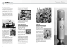
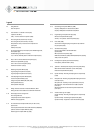
Despite all the progress in machines and pro-
duction technology, manufacturing a high-qual-
ity microphone involved a great deal of hand-
icraft, upon which the quality of these trans-
ducers and a reputation such as Neumann’s
ultimately depend.
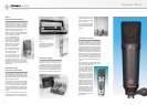
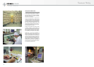
Capsule Building – A Science in Itself
The performance of the condenser microphone,
now manufactured in an extremely wide range
of models, remains largely reliant on the preci-
sion engineering involved in capsule production.
The common centre electrode found on a dou-
ble diaphragm capsule contains a large number
of critical drill holes, some of which are blind.
The depth of these blind holes determines the
volume of air trapped behind the diaphragm.
This volume, which inhibits the movements of
the diaphragm, determines the transducing ca-
pability of the condenser microphone.
The dimensions of the holes, and their accurate
machining becomes even more crucial when the
electrode is produced in two halves. With this
design the two halves of the capsule can be elec-
trically connected, and similarly separated, by
means of an isolating intermediate layer, there-
by making it possible to switch the directional
characteristic with the available polarisation
voltage.
To smooth the surface of the electrodes two dif-
ferent processes are employed. For microphone
capsules whose surface lie on one plane a lap-
ping process can achieve a surface flatness of
0.3 µm and a plane parallelism of +/– 1 µm be-
tween the front and the back of the electrode.
In some cases a capsule’s surface may be in two
planes. This may be because the distance be-
tween the diaphragm and the electrode has al-
ready been determined by the second plane of
the electrode. In such cases the finishing is per-
formed on special lathes.
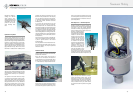
After lapping or lathe finishing, the holes must
be deburred, followed by a visual inspection us-
ing a powerful microscope.
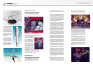
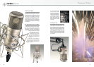
Diaphragms are made from a 6.3 µm thick pol-
yester foil, such as Mylar. This is first attached
to brass rings, then put into a container which
holds it while gold is applied under vacuum to
a uniform layer 300 Angstroms thick (0.03 µm).
The external diameter of the capsule is approx-
imately 34 mm. The diaphragm is fitted approx-
imately 40 µm in front of the electrode and is
6.3 µm thick. When a sound pressure of 1 Pa is
applied the diaphragm movement is no more
than 10 nm. By comparison, the wavelength of
violet light is 400 nm.
The mechanical advantages being achieved un-
der these microscopic proportions is best put
into perspective by illustrating thus: if a mi-
crophone capsule were to be given a scale on
which the amplitude for 1 Pa were represented
by 1 mm the capsule under manufacture would
have to have a diaphragm spacing of 4 m, and
the diameter of the capsule would be more than
3km.
One type of capsule, the KK 88 from the KM 88
microphone, uses pure nickel as the diaphragm
material 0.0007 mm thick (0.7 µm).
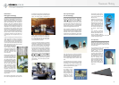
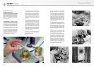
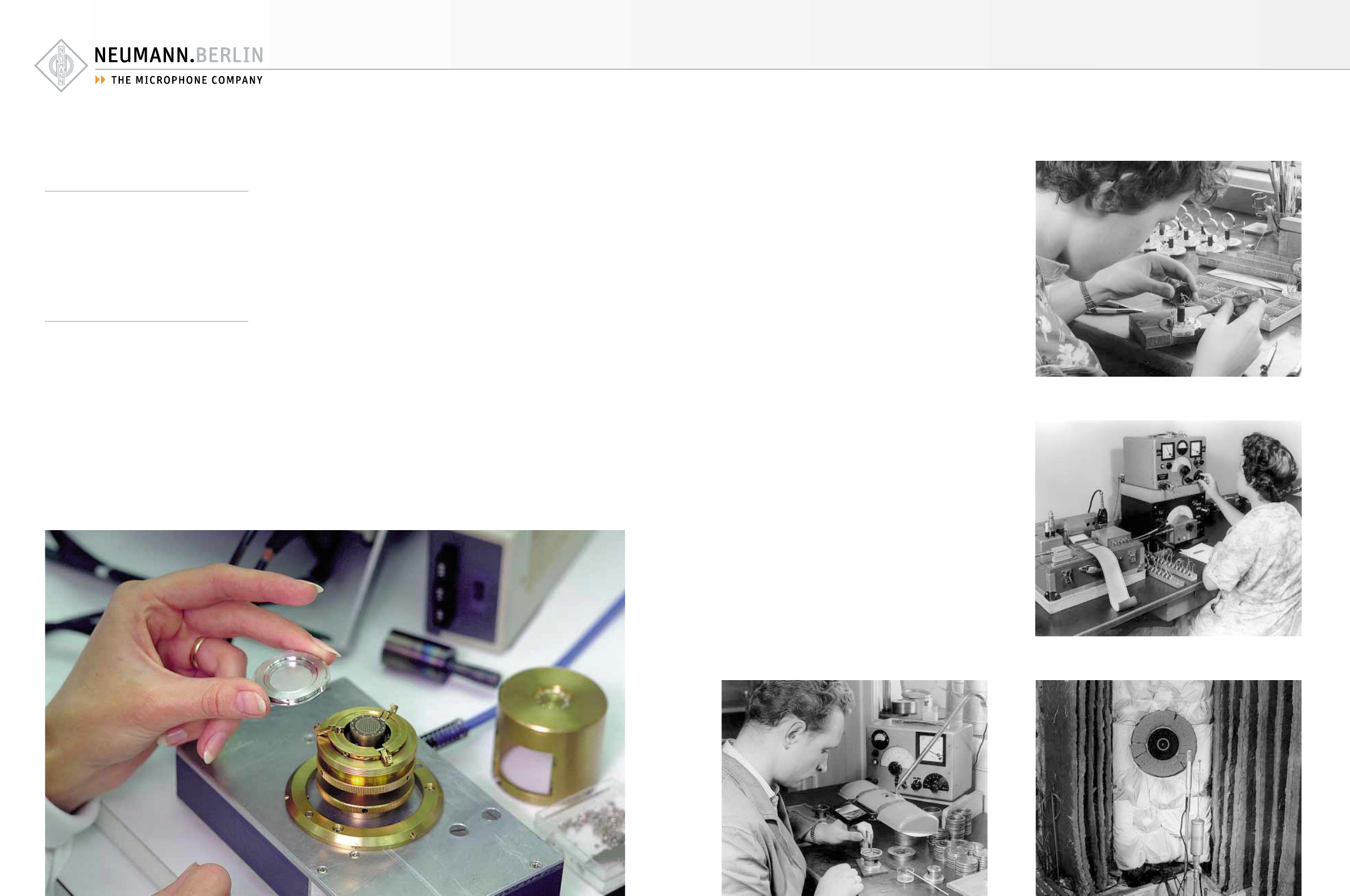
On assembly of the capsule aluminium foil spac-
er rings, 40 µm thick are attached to the mid-
dle and the edge of the electrode. The lead-in
contact for the polarisation voltage is fitted in
the centre. This is an assembly device that en-
ables the capsule to be directly connected to a
test instrument, with which the capacitance is
measured and the mechanical strength of the
diaphragm tested. This is done by measuring
the change in the basic capacitance after the
polarisation voltage has been applied.