


Far
microphones
equipped with connectors per
DIN
41524
(Binder,
Mini-
Tuchel), the following changes
are necessary:
1.
Wire heretofore soldered to pin 3 (-1 is to
be
resoldered to pin. 2
without
removing
the
wire already
connected
there.
2.
Wire
heretofore
connected to pin 1
(+> is to bt-: resoldered to
pin 3.
3. Remove the Phantom pawering
resistors.
4. Install a
new
wire
from the
junction
of these
resistors
to pin 1.
The
circuit
then
corresponds to DIN 45594
Type L.
The
IC 3, IC 4,
KT
1 tiicrophone Cables require
no changes.
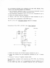
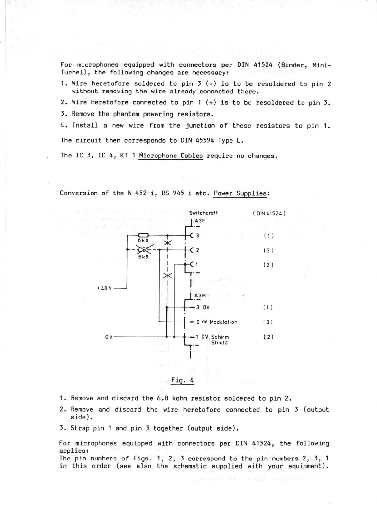
Conversion
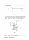
of the N 452 i, BS 945 i etc. Power Supplies:
+L8V-
.-
+4--
6k8
J
Switchcraft
A3F
1-
6k8
T
I
1
x
/
-t:
I
ov
T
1
i’-
A3M
.-
#
.
3 ov
.
+
2 w Modulation
-&=l OV, Schirm
L,-
Shield
i
Fig. 4
11)
12 1
11)
131
(2)
1. Remove and
discard
the 6.8 kohm
resistor soldered
to pin 2.
2. Remove and
discard
the
wire heretofore
connected to pin 3 (output
side).
3. Strap
pin 1 and pin
3 together
(output
side).
For microphones
equipped with
connectors per
DIN 41524, the following
applies :
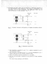
The pin numbers
of
Figs, 1, 2, 3 correspond
to the pin numbers 2, 3, 1
in this
order
(sec also the schematic
supplied
with
your
equipment) .