


5
4
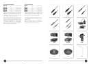
ter Armatur. Andere Kabellängen oder Kabelmaterial
ohne Armaturen sind auf Wunsch lieferbar. Die aku-
stischen Eigenschaften der Mikrophone werden auch
durch sehr lange (Neumann-) Kabel nicht beeinflußt.
Erst bei Kabellängen deutlich über 300 m macht sich
ein Abfall im oberen Frequenzbereich bemerkbar. Die
Mikrophone der Serie „fet 100
®
“ sind besonders un-
empfindlich gegen kapazitive Belastung. TIM- und Fre-
quenzgangverzerrungen werden daher auch bei Ver-
wendung sehr langer Kabel nicht hervorgerufen.
ICIC
ICIC
IC
3131
3131
31
mt (5mt (5
mt (5mt (5
mt (5
m)m)
m)m)
m) ............... sw .............................Best.-Nr. 06570
5 m langes Mikrophonkabel, Durchmesser 4,5 mm, mit
Doppeldrallumspinnung als Abschirmung. Schwarzmat-
te 3-polige XLR-Steckverbinder. Zur Vermeidung von
Reibgeräuschen bei der Verwendung an der Angel
oder an Kunststoffdurchführungen (z.B. bei Windschutz-
körben) ist das Kabel textilumsponnen.
ACAC
ACAC
AC
22 (0,322 (0,3
22 (0,322 (0,3
22 (0,3
m)m)
m)m)
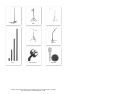
m)........................................................ Best.-Nr. 06598
Adapterkabel mit einer 5-poligen XLR-Buchse und ei-
nem 3,5 mm Stereoklinkenstecker, unsymmetrisch, für
den Anschluß des 5-poligen XLR-Ausganges des Spei-
segerätes BS 48 i-2 oder der Matrixbox MTX 191 A
an Geräte mit 3,5 mm Stereoklinkenbuchse. Vorge-
sehen für alle Mikrophone der Serien fet 80/100 und
KM 100 F mit Ausnahme der Ausgangsstufe KM 100
und des GFM 132.
ACAC
ACAC
AC
25 (0,325 (0,3
25 (0,325 (0,3
25 (0,3
m)m)
m)m)
m)........................................................ Best.-Nr. 06600
Adapterkabel mit einer 3-poligen XLR-Buchse und ei-
nem 6,3 mm Monoklinkenstecker, unsymmetrisch, für
den Anschluß des 3-poligen XLR-Ausganges eines
Speisegerätes BS 48 i oder N 48 i-2 an Geräte mit
6,3 mm Monoklinkenbuchse. Vorgesehen für alle
fet 80/100-Mikrophone und KM 100 F mit Ausnahme
der Ausgangsstufe KM 100 und des GFM 132.
ACAC
ACAC
AC
27 (0,327 (0,3
27 (0,327 (0,3
27 (0,3
m)m)
m)m)
m)........................................................ Best.-Nr. 06602
Y-Kabel mit einer 5-poligen XLR-Buchse und zwei
6,3 mm Monoklinkensteckern, unsymmetrisch, für den
Anschluß des 5-poligen XLR-Ausganges eines Spei-
segerätes BS 48 i-2 oder der Matrixbox MTX 191 A
an Geräte mit 6,3 mm Monoklinkenbuchsen. Vorge-
sehen für alle fet 80/100-Mikrophone und KM 100 F
mit Ausnahme von KM 100 und GFM 132.
Andere Kabellängen sind auf Wunsch lieferbar.
6. Stromversorgung
6.1 Phantomspeisung
Die Mikrophone der Serie „fet 100
®
“ werden mit 48 V
phantomgespeist (P48, IEC 1938). Bei der Phantom-
speisung fließt der Speisestrom vom positiven Pol der
cable lengths or cable materials without connectors
can be supplied to order. The electroacoustic proper-
ties of the microphones are not affected by very long
(Neumann) cables. It is only when cables are well
over 300 m that any fall-off in the upper frequency
range becomes apparent. The microphones of the “fet
100
®
” Series are highly insensitive to capacitive load-
ing. As a result, even very long cable runs do not
cause either TIM or frequency distortion.
ICIC
ICIC
IC
3131
3131
31
mt (5mt (5
mt (5mt (5
mt (5
m)m)
m)m)
m) ............... sw .............................. Cat. No. 06570
5 m langes Mikrophonkabel, Durchmesser 4,5 mm, mit
Doppeldrallumspinnung als Abschirmung. Schwarzmat-
te 3-polige XLR-Steckverbinder. Zur Vermeidung von
Reibgeräuschen bei der Verwendung an der Angel
oder an Kunststoffdurchführungen (z.B. bei Windschut-
zkörben) ist das Kabel textilumsponnen.
ACAC
ACAC
AC
22 (0.3 m)22 (0.3 m)
22 (0.3 m)22 (0.3 m)
22 (0.3 m) ....................................................... Cat. No. 06598
Adapter cable with a 5-pin XLR connector on one
end and an unbalanced 3.5 mm stereo jack on the
other end. It is used to connect the 5-pin XLR out-
put of the BS 48 i-2 power supply or the MTX 191 A
matrix amplifier to units with a 3.5 mm stereo input.
It is designed for all microphones of the fet 80/100
series and KM 100 F, excluding the KM 100 and the
GFM 132.
ACAC
ACAC
AC
25 (0.3 m)25 (0.3 m)
25 (0.3 m)25 (0.3 m)
25 (0.3 m) ....................................................... Cat. No. 06600
Adapter cable with 3-pin XLR connector and a 6.3 mm
monojack, unbalanced. It is used to connect 3-pin XLR
outputs of the BS 48 i or N 48 i-2 power supplies to
units with a 6.3 mm monojack input. Designed for all
microphones of the fet 80/100 series and KM 100 F,
excluding the KM 100 output stage and the GFM 132
boundary-layer microphone.
ACAC
ACAC
AC
27 (0.3 m)27 (0.3 m)
27 (0.3 m)27 (0.3 m)
27 (0.3 m) ....................................................... Cat. No. 06602
Y-cable with a 5-pin XLR connector and two 6.3 mm
monojacks, unbalanced. It is used to connect 5-pin
XLR outputs of the BS 48 i-2 power supply or the
MTX 191 A matrix amplifier to units with 6.3 mm
monojack inputs. Designed for all microphones of the
fet 80/100 series and KM 100 F, excluding the KM 100
and the GFM 132.
Custom-made cables are available on request.
6. Power Supply
6.1 Phantom Powering
The “fet 100
®
” Series microphones are phantom-pow-
ered at 48 V (P48, IEC 1938). With phantom power-
ing the dc from the positive supply terminal is divid-
3. Einige Zusatzinformationen zum
Betrieb
Der im Mikrophon eingebaute DC-DC-Wandler ver-
sorgt im Gegensatz zu bisherigen Schaltungskonzep-
ten auch den NF-Verstärker und nicht nur die Mikro-
phonkapsel. Da dieser Wandler Änderungen der
Versorgungsspannung ausregelt, versucht er dies auch,
wenn das Netz abgeschaltet wird. So bleibt die inter-
ne Spannung des Mikrophons noch ca. 2 Sekunden
erhalten, ehe sie mit einem hörbaren „Blubb“ zusam-
menbricht, gefolgt von einem kurzen Rauschen.
Vergleichbare Geräusche können auch beim Einschal-
ten der Stromversorgung auftreten und es dauert eini-
ge Sekunden, bis das Mikrophon übertragungsbereit ist.
Die meisten anderen Mikrophone haben keine vergleich-
bare „innere Spannungsversorgung“, so daß deren Ver-
stärker den Aufbau bzw. das Zusammenbrechen der
Polarisationsspannung nicht übertragen können.
Die Funktion „–10 dB“ wird bei den Mikrophonen
KMS 140 und KMS 150 nicht durch Umschaltung der
Gegenkopplung im Verstärker erreicht, wie bei Mikro-
phonen der Serie „fet 80
®
“, sondern durch Verrin-
gern der Kapselvorspannung. Dieser Umladevorgang
dauert einige Sekunden, während derer das Mikro-
phon stummgeschaltet ist.
Das Zurückschalten zum vollen Übertragungspegel
kann, wie beim Einschalten des Mikrophons, mit ei-
nem kurzen Rauschen verbunden sein, bedingt durch
den oben beschriebenen Aufladevorgang.
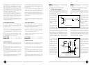
4. Beschaltung des
Mikrophonausgangs
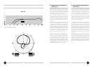
Die Zuordnung des Mikrophonanschlusses entspricht
DIN 45 599, Kennzeichen „I“ bzw. IEC 268-12 (pin.
conn. 130-x-IEC 02):
Die Modulationsadern liegen an Stift 2 und 3, die Ab-
schirmung an Stift 1.
Bei einem Schalldruckanstieg vor der Mikrophonmem-
bran tritt an Stift 2 eine positive Spannung auf.
5. Mikrophonkabel
IC 3 mtIC 3 mt
IC 3 mtIC 3 mt
IC 3 mt ................................. sw ..............................Best.-Nr. 06543
10 m langes Mikrophonkabel ohne Stativgelenk (Switch-
craftkupplungen), es kann auch als Verlängerungskabel
verwendet werden. Mikrophonseitig mit schwarzmat-
3. Additional Hints for
Operating
The dc-dc converter installed in the microphone sup-
plies in contrast to other circuit conceptions also the
audio amplifier and not only the microphone capsule.
Since this converter compensates for variation of the
supply voltage it tries to do this also when the ac
main is switched off. Therefore the internal supply
voltage of the microphone is maintained for approxi-
mately 2 seconds before it collapses with an audible
“blubb” followed by a short noise.
Noises comparable to this can be recognized also
when switching the supply on and it takes some sec-
onds until the microphone is ready to operate.
Most of other microphones have no similar “internal
power supply” so that those amplifiers cannot trans-
mit the building up or breakdown of the polarizing
voltage.
The “–10 dB” function is not realized by changing
the negative feedback in the amplifier of the KMS 140
and KMS 150 microphones as is done with micro-
phones of the “fet 80
®
” series but by diminishing of
the capsule polarizing voltage. This procedure may last
some seconds during which the microphone is mute.
Returning to the full transmission level the microphone
can – as it is the case when switching it on – be
accompanied by a short noise caused by the above
mentioned increase of the polarizing voltage.
4. Microphone Output
Wiring
Microphone wired per IEC 268-12 (pin conn. 130-x-
IEC 02) or DIN 45 599 I, respectively:
Modulation is connected to pins 2 and 3, the shield
to pin 1.
A sudden sound pressure rise in front of the mem-
brane causes a positive voltage to appear at pin 2.
5. Microphone Cables
IC 3 mtIC 3 mt
IC 3 mtIC 3 mt
IC 3 mt ................................. blk.............................. Cat. No. 06543
10 m microphone cable without stand mount (Switch-
craft couplings) can also be used as extension cable.
With matt black connector at microphone end. Other