


6 7
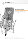
M 149 Tube
Nach wenigen Minuten hat die Röhre im M 149 Tube
ihren stabilen Betriebszustand erreicht und weist
dann ihren besonders niedrigen Eigengeräuschpe-
gel auf.
Beim Umschalten der Richtcharakteristik tritt für
einen Zeitraum bis ca. 30 s ein erhöhter Rausch-
pegel auf. Dieser entsteht durch die Umladung der
Kapsel auf die jeweils notwendige Vorspannung.
Eine eventuell anliegende externe Phantomspei-
sung beeinträchtigt die Funktion des M 149 Tube
nicht. Wird eine externe Phantomspeisung an- oder
abgeschaltet, ergibt sich kurzzeitig ein leicht er-
höhter Eigengeräuschpegel.
Der Netzschalter des Netzgerätes unterbricht die
Zuleitungen des eingebauten Netzteiles sekundär-
seitig. Zur Stromersparnis sollte das Netzgerät bei
längerer Nichtbenutzung vom Stromnetz getrennt
werden.
Zum Schutz des Mikrophons bei Nahbesprechung
wird die Verwendung eines Popschutzes PS 15
oder PS 20 a empfohlen. Nähere Angaben dazu im
Kapitel „Zubehör“.
2.3 Ausführungsform und Beschaltung des
Mikrophon- und Netzgeräteausganges
Das Mikrophon kann in folgenden Ausführungsfor-
men geliefert werden:
M 149 Tube (EU) ...... ni ........ Best.-Nr. 08390
M 149 Tube (US) ...... ni ........ Best.-Nr. 08399
M 149 Tube (UK) ..... ni ........ Best.-Nr. 08403
Das Mikrophon hat eine nickelmatte Oberfläche.
Der 8-polige Stecker des Mikrophons und des
Netzgerätes ist folgendermaßen beschaltet:
Pin 1: –70 V
Pin 2: +5 V
Pin 3: Modulation (+Phase)
Pin 4: +70 V
Pin 5: Sensorleitung
Pin 6: Masse
Pin 7: +32 V
Pin 8: Modulation (–Phase)
Das zum Lieferumfang gehörende 8-polige Kabel
verbindet das Mikrophon mit dem Netzgerät.
Within a few minutes, at the latest, the tube in the
M 149 Tube reaches its stable operating condition
and then evidences its particularly low residual
noise level.
When switching the directional characteristic, an
elevated noise floor can be noticed for 30 s max.
This is due to the reloading of the capsule to the
appropriate polarization voltage.
External phantom power, if present, does not de-
tract from the performance of the M 149 Tube. If an
external phantom power source is switched on or
off, only a short, slight rise in the residual noise
level will result.
The on/off switch of the power supply functions as
a secondary voltage interrupt for the feeds from
the built-in mains unit. To save energy, the pow-
er supply should be unplugged from the wall out-
let if it goes unused for an extended period.
To protect the microphone in close miking appli-
cations we recommend using a pop screen PS 15
or PS 20 a. For details, see the topic “Accesso-
ries”.
2.3 Type and Configuration of the Microphone and
Power Supply Outputs
The following versions of the M 149 Tube micro-
phone are available:
M 149 Tube (EU) ..... ni .......... Cat. No. 08390
M 149 Tube (US) ..... ni .......... Cat. No. 08399
M 149 Tube (UK) ..... ni .......... Cat. No. 08403
The microphone is finished in matt nickel. The
8-pin connector of the microphone and the corre-
sponding connector of the power supply unit have
the following configuration:
Pin 1: –70 V
Pin 2: +5 V
Pin 3: audio signal (+phase)
Pin 4: +70 V
Pin 5: sensor line
Pin 6: ground
Pin 7: +32 V
Pin 8: audio signal (–phase)
The included eight-core cable connects the micro-
phone to the power supply unit.
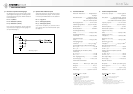
Die Modulation liegt hier an einem 3-poligen
XLR-Stecker. Erforderliches Gegenstück: XLR 3 F.
Die Zuordnung der Mikrophonanschlüsse ent-
spricht DIN EN 60268-12 bzw. IEC 60268-12:
Bei einem Schalldruckanstieg vor der vorderen
Mikrophonmembran tritt an Pin 2 eine positive
Spannung auf.
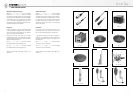
2.4 Mikrophonkabel
Für das M 149 Tube stehen folgende Kabel zur Ver-
fügung:
KT 8 (10 m) ....... sw ............ Best.-Nr. 08407
(gehört zum Lieferumfang)
Kabel für M 147/M 149/M 150 Tube mit Doppel-
drallumspinnung als Abschirmung. Ø 5 mm, Länge
10 m. DIN 8-Steckverbinder.
IC 3 mt ............... sw ............ Best.-Nr. 06543
Mikrophonkabel mit Doppeldrallumspinnung als
Abschirmung. Ø 5 mm, Länge 10 m. XLR 3 Steck-
verbinder, schwarzmatt.
Andere Kabellängen sind auf Wunsch lieferbar.
Das Mikrophon ist besonders unempfindlich gegen
kapazitive Belastung. TIM- und Frequenzgangver-
zerrungen werden auch bei Verwendung sehr lan-
ger Kabel nicht hervorgerufen. Daher sind für die
Modulation Kabellängen bis etwa 300 m erlaubt.
Das 8-polige Kabel zwischen Mikrophon und Netz-
gerät darf dabei bis etwa 100 m lang sein.
3. Netzgerät
Das Universal-Netzgerät N 149 A kann in folgen-
den Ausführungsformen geliefert werden:
N 149 A EU ......... sw ............ Best.-Nr. 08447
N 149 A US ......... sw ............ Best.-Nr. 08446
N 149 A UK ......... sw ............ Best.-Nr. 08448
Die unterschiedlichen Versionen der Netzgeräte
unterscheiden sich lediglich durch ihre Netzkabel.
Das Vintage-Netzgerät N 149 V kann in folgenden
Ausführungsformen geliefert werden:
N 149 V EU ............................ Best.-Nr. 08540
N 149 V US ............................ Best.-Nr. 08541
N 149 V UK ........................... Best.-Nr. 08542
Die unterschiedlichen Versionen der Netzgeräte
unterscheiden sich lediglich durch ihre Netzkabel.
At the power supply unit, the audio signal is avail-
able at a 3-pin XLR socket which requires an
XLR 3 F connector. The microphone is wired as per
DIN EN 60268-12 or IEC 60268-12:
An increase in sound pressure at the microphone‘s
front diaphragm produces a positive voltage at
pin 2.
2.4 Microphone Cables
The following cables are available for the
M 149 Tube:
KT 8 (10 m) ....... blk ............. Cat. No. 08407
(included in the supply schedule)
Cable for M 147/149/150 Tube, with double twist
(double helix) braiding as shield. Ø 5 mm, length
10 m. DIN 8 connectors.
IC 3 mt ................ blk ............. Cat. No. 06543
Microphone cable with double twist (double helix)
braiding as shield. Ø 5 mm, length 10 m. XLR 3
connectors, matte black.
Custom-made cables are available on request.
The microphone is especially insensitive to ca-
pacitive loads. Even the use of long cables does
not cause TIM or frequency response distortions.
Thus, the audio signal cable can have a length of
up to approx. 300 m, the 8-core connecting cable
between the microphone and the power supply
unit can be as long as approx. 100 m.
3. Power Supply Unit
The N 149 A power supply unit is available in the
following versions:
N 149 A EU.......... blk ............. Cat. No. 08447
N 149 A US .......... blk ............. Cat. No. 08446
N 149 A UK ......... blk ............. Cat. No. 08448
The three available versions of the N 149 A just
differ in their enclosed mains power cable.
The N 149 V vintage power supply unit is avail-
able in the following versions:
N 149 V EU.............................. Cat. No. 08540
N 149 V US.............................. Cat. No. 08541
N 149 V UK ............................. Cat. No. 08542
The three available versions of the N 149 V just
differ in their enclosed mains power cable.