


1010
EN
1111
EN
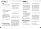
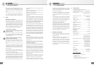
9. Troubleshooting
Problem
▶
Possible causes
▶
Solution
Microphone not
operating /
No signal
transmission
Supply voltage not activated Check the power supply device and if necessary
the associated software settings (RCS -> System ->
MicPWR).
The microphone is not connected
to an AES 42 input
Use an AES 42 input.
The microphone is not connected
to the right channel
Check the signal path.
If necessary, activate the appropriate input on the
corresponding channel of the mixing console.
The channel is muted Deactivate the mute in the AES 42 remote control.
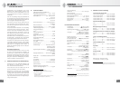
Distorted
sound /
bad signal
quality
Excessive sound pressure of the
signal to be recorded
Take a more distant microphone position or activate
the pre-attenuation in the AES 42 remote control.
Overload due to low-frequency
interference (e.g. impact sound
or wind)
Use an appropriate windscreen (accessory). Activate
the pre-attenuation in the AES 42 remote control.
Overloading due to Plosives Use an appropriate popscreen (accessory). Activate
the pre-attenuation in the AES 42 remote control.
Sound is mu ed
and reverberant
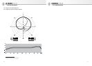
Incorrect directional
characteristics
Check to ensure that the microphone is being
addressed from the correct side, as designated by the
Neumann logo
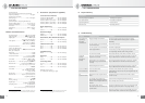
No
synchronization
Operation is set to asynchronous
mode
Activate the synchronization of the AES 42 input
(mode 2, RCS).
The sample rates of the micro-
phone and the subsequent equip-
ment do not correspond with one
another
Synchronize the digital input with the source.
Use a sample rate converter.
An external word clock is
detected but does not conform to
specifi cations
Check the external word clock for precision and signal
quality (e.g. check for jitter or very long cables).
Alternative solution: Use the internal DMI word clock
as the master word clock for the entire signal chain.
Synchronization
Free-running (non-synchronous operation),
frequency stability ................................... ± 25 ppm
Synchronous operation,
pulling range .................................. min. ± 100 ppm
Power supply
(phantom power complying with AES 42)
Supply voltage range .......................+7 V to +10.5 V
Current consumption .........................max. 150 mA
Connector ..................................................... XLR 3 M
Dimensions ......................................Ø 60 x 132 mm
Weight .............................................................460 g
Remote controlled functions
Pre-attenuation ..........................0/–6/–12/–18 dB
High-pass fi lter ..........................Off /40/80/160 Hz
Digital gain .........................................0...10...63 dB
in steps of 1 dB, clickless
Test signals ..........................Off , 1 kHz (–48 dBFS),
Pink noise (–35 dBFS),
White noise (–43 dBFS)
Compressor/Limiter ..................................... On/O
Lower cut-o frequency
of the working range ..........Flat/1 kHz/2 kHz/4 kHz
Max. gain reduction:
Flat mode ...................................................... > 63 dB
1 kHz/2 kHz/4 kHz ........................................> 20 dB
Compression ratio .........................1.2:1/1.5:1/2:1/
3:1/4:1/6:1/8:1/>100:1
Threshold .......................–63 dBFS...–10...0 dBFS,
in steps of 1 dB
Attack time ............. 0/0.1/0.3/1/3/10/30/100 ms
Release time ..................0.05/0.1/0.2/0.5/1/2/5 s
(for a level change of approx. 10 dB )
Peak limiter ................................................... On/O
Threshold ......................................O : 0 dBFS fi xed
On: –15 dBFS to 0 dBFS,
in steps of 1 dB
Attack time .................................–160 s (negative)
Release time .................. Approx. 50 ms to 150 ms
(signal-dependent)
Mut e ............................................................... On/Off
Phase (polarity) .........................................0°, 180°
Signal light .............................................LED (blue),
brightness adjustable
Sampling rates .................................44.1/48/88.2/
96/176.4/192 kHz
(Factory setting depending on version supplied.)
Factory settings are indicated in bold. If the DMI is used, they
can be changed at any time via the Remote Control Software.
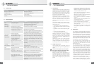
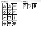
7. Accessories* (see photos in appendix)
Connection Kits & Interface
Connection Kit AES/EBU..............Cat. No.
Connection Kit S/PDIF .................Cat. No.
Interface, DMI- ( V, EU) .......Cat. No.
Interface, DMI- ( V, UK) .......Cat. No.
Interface, DMI- ( V, US) .......Cat. No.
Elastic Suspensions
EA 1 ..........................ni ..................Cat. No. 008449
EA 1 mt .....................blk ................Cat. No. 008450
Auditorium Hanger
MNV 87 ....................ni ..................Cat. No. 006804
MNV 87 mt ...............blk ................Cat. No. 006806
Stand Mounts, Misc. Mechanical Adapters
DS 120 .....................blk ................Cat. No. 007343
SG 1 ..........................blk ................Cat. No. 008445
Table and Floor Stands
MF 3..........................blk ................Cat. No. 007321
MF 4 .........................blk ................Cat. No. 007337
MF 5 .........................gry ................Cat. No. 008489
Foam Windscreens
WS 87 .......................blk ................Cat. No. 006753
Popscreen
PS 15 .......................blk ................Cat. No. 008472
PS 20 a ...................blk ................Cat. No. 008488
Connecting Cables
IC 3 mt ....................blk ................Cat. No. 006543
IC 4 ...........................ni ..................Cat. No. 006547
IC 4 mt .....................blk ................Cat. No. 006557
Meaning of color codes:
ni = nickel, blk = black, gry = grey
* Detailed descriptions and additional articles can be found
in our accessories catalog or at: www.neumann.com
8. Scope of delivery
Microphone Starter Set
TLM 103 D (mt) microphone TLM 103 D microphone
SG 1 stand mount EA 1 elastic suspension
Operating manual Connection Kit
Wooden case Operating manual