


DM 1685
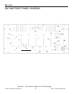
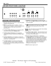
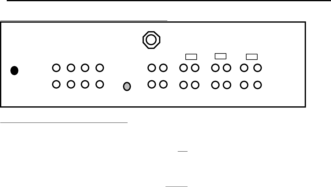
DM1685 REAR PANEL DIAGRAM
1
4 5 3
2
10
7
8
99 97 7 7 7
8
8
6
REAR PANEL: INPUTS AND OUTPUTS
1. AC Cord. See safety precautions on page 2 for proper
treatment of the power cord.
2. GND is the grounding lug for turntables 1, 2 and 3
(phono inputs on Channels 1, 2 and 3). Always use this
connection (your turntable cable should have a
grounding wire).
3. The Stereo Main Outputs are low-impedance RCA
connectors controlled by the Master fader.
4. The Stereo Zone Outputs are low-impedance
unbalanced RCA jacks controlled by the Zone Level
control.
5. The Tape Outputs are low-impedance unbalanced
RCA jacks which output the program mix and allow you to
connect any recording device.
6. The Send output is for send to an external signal
processor such as an external sampler or effects box.
You direct sound to the send by pressing the send button
on the main panel.
7. Channels 1-5 Line Inputs are unbalanced RCA
jacks. The Line Input is selected with the toggle switch
on the front panel.
You can connect stereo audio from HiFi VCRs, cassette and
reel-to-reel tape decks, DAT machines, CD players, laser
discs, tuners, even synthesizers or other mixing
consoles.
NOTE: Plug mono audio sources into both Left and Right
inputs using a “Y” cable connector.
8. Line/Phono Input switch. Use this to allow line level
equipment to be plugged into your phono inputs giving
you a total of 8 line input options.
9. Phono Inputs on Channels 1, 2 and 3 use
unbalanced RCA jacks. Your input signal is fed directly to
the DM1685's high-quality RIAA phono pre-amplifiers
so use this position only for moving magnet cartridges.
Line level sources will overload the sensitive phono pre-
amps and will sound very bad, so always be sure to
toggle the line/phono switch over to line before
connection of line sources.
10. Mic 2 is the mic input for mic 2.
Numark - The Proven Leader in DJ Technology
©1997 Numark Industries 12 http://www.numark.com